TELEPHONE – T1/DSL/FTTx
As everyone is probably well aware of, changes in communication are coming fast and furious. The addition of cellular towers is very obvious, but there are even more drastic changes occurring underground that deal with the communication systems connecting to homes and businesses. The purpose of this page is to hopefully give a rough idea of what has been happening and how it relates to the aboveground structures.
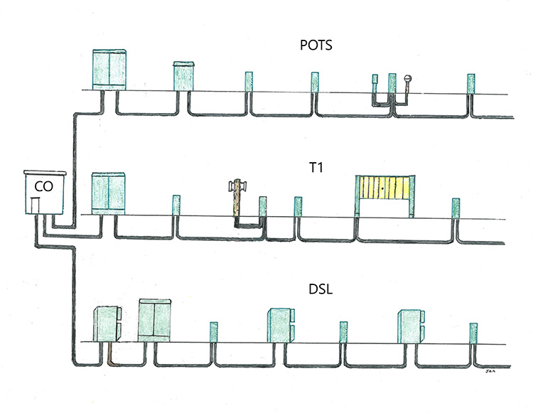
Besides POTS, there are also three other types of telephone systems. T1 uses specialized cables and occasional cabinets to increase bandwidth, and was specifically designed for video conferencing and picture phones. DSL uses phone cables already in place, but with regularly spaced new cabinets to increase the bandwidth, and allows phone cables to carry internet and Cable TV. FTTx is any communication system that includes at least some fiber optic cable. All of these systems can also provide telephone service.
TRANSMISSION ONE SYSTEM – T1
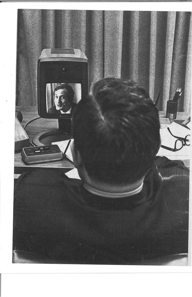
This was the first communication system that could provide video conferencing. T1 was introduced in 1963, and it was an abbreviation for Transmission One. The T1 system had a much broader bandwidth, and that in turn allowed picture and audio signaling in both directions.
The T1 system was advertised to businesses for video conferencing and to the public to provide picture phones. Picture phones never took off in popularity, and it became a very short-lived service. Even today most people do not like Skype calls. However, video conferencing was used by many businesses.
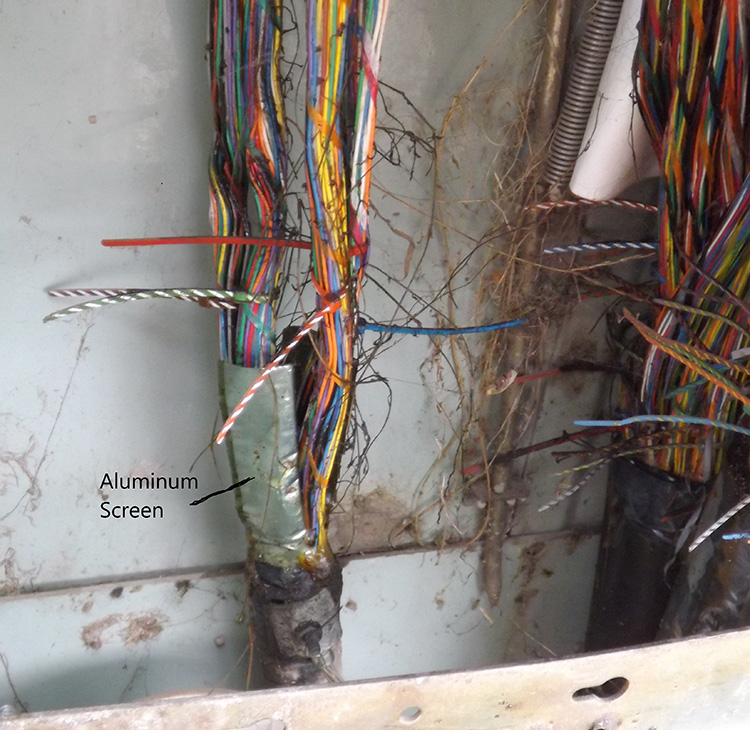
Telephone cables had never been able to handle multiplexing, mainly because of their twisted pair construction. Twisted pair construction was excellent for single frequency communication, but it wrecked havoc with multiple frequency communication. This was from the fact that at every bend of the cable, the individual conductors would end up being spaced slightly different than they would in a straight cable, and this would cause fluctuations in the current. This would usually be a difference of less than a single millimeter, but it was enough to ruin the signal. The answer was to separate the tip wires from the ring wires with an aluminum screening, so for the first time the send and receive would be isolated, and therefore prevent fluctuations in the signal. These screened cables are the only cables that are not twisted pair, but isolated pair.
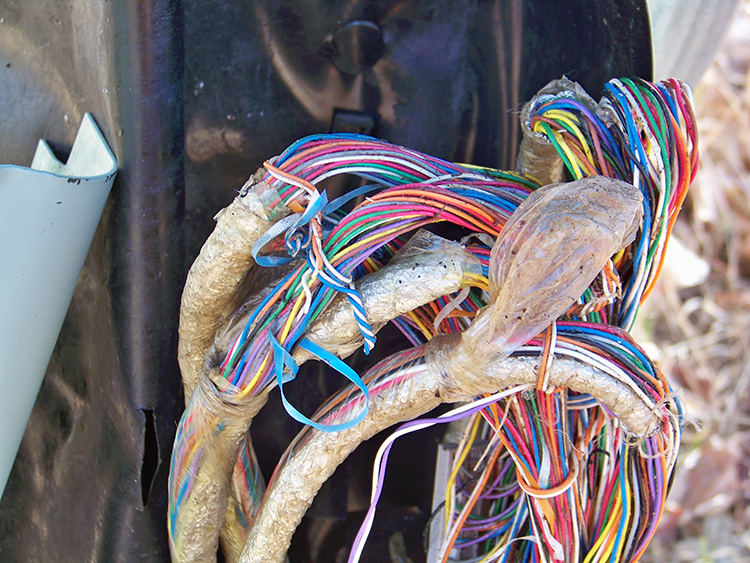
T1 cables could also handle 24 voice channels per phone pair. This meant that a 100 pair screened cable could handle 2400 phone conversations simultaneously. However, these T-screen cables were never actually built in the 25 pair bundles. They always had an unusual pair number. There were several different sizes of cables that were especially produced to handle the T1 system, and all of them were produced in very unique pair counts including: 26, 54, 106, and 206. The original T-screen cables also have the same 4-letter code, KJAW. This is because they were constructed with the screened core cable, 22 gauge conductors, gel-filled insulation, and a polypropylene outer sheath instead of the standard polyethylene. The gel, or “jelly” is of course only a nickname for the waterproofing substance that is in between the conductor and the polypropylene covering of the conductor. So, a T-screen cable code becomes easily identifiable, such as KJAW-26, or the later T-2 systems with a KGAW-26.
There are 4 known cable codes for T-screens: KJAW – KFAW – KGAW – MFMW. So, a T-screen cable can be a KJAW-26, a KGAW-210, or a number of other possibilities.
A T1 system can extend only about 30 miles. Along that route, there will be T1 repeaters. These have a slightly different look than POTS repeaters. T1 repeaters must be spaced no more than a little over a mile apart (6000 feet). The T1 repeaters are white like most other repeaters, but they have an appearance of being two boxes attached together.
T1 systems do not use load coils. They also have a T1 special cabinet that would alter the T1 signals to POTS. However, those T1 cabinets are occasionally used to house other communication electronics.
DIGITAL SUBSCRIBER LINE – DSL
T1 used specifically designed cabinets and repeaters, but they also required specifically constructed cables which had to be placed in the ground. So, although T1 offered broadband capabilities, it was very expensive to install.
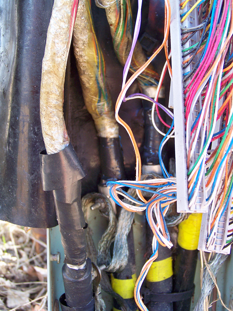
The major difference with DSL is its capability to use the preexisting cables in the ground. The value of DSL was based on a statistic that claimed there were 800 million telephone cable splices throughout the world in the late 1980’s. What this meant was that there was already a wonderful supply of communication lines throughout the world, and even a wonderful supply of easy connections to those lines at the pedestals.
If you simply removed some of the pedestals and replaced them with a device that could regenerate the signal, then the cost of transforming that old analog telephone cable into a digital broadband cable would be very reasonable.
With DSL the digital signal begins at the CO, and is then regenerated at DSL cabinets at regular intervals. Now a 50-year old telephone cable that is already underground can be used to transmit a broadband signal giving them the capability to transmit high speed internet, cable TV programming, and more, but that alteration has limitations in distance, and the limitation is four and a half miles. A DSL cabinet must be placed at a maximum of every 4.5 lineal miles along the route for regeneration. That cabinet is called a DSL cabinet, and more commonly a DSLAM for Digital Subscriber Line Access Multiplexer. They may also be called Remote DSLAMs since they are outside of the CO.
These DSLAMs are also commonly referred to as concentrators or multiplexers. Of course, the old T1’s were also multiplexers because they increased the capability of the cable.
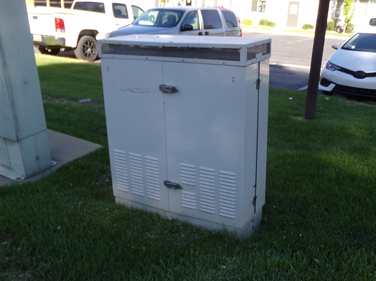
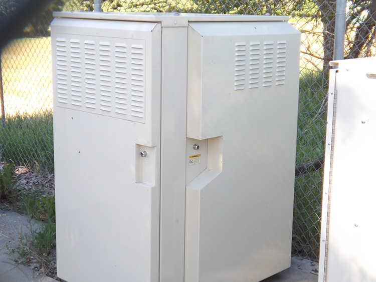
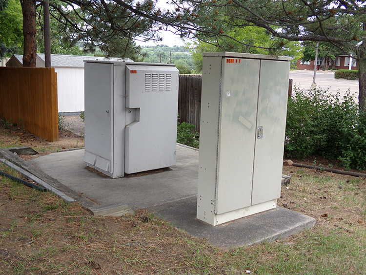
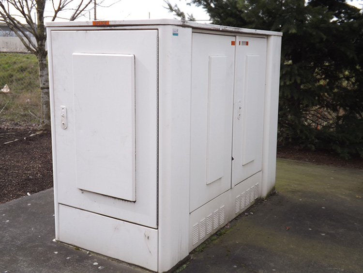
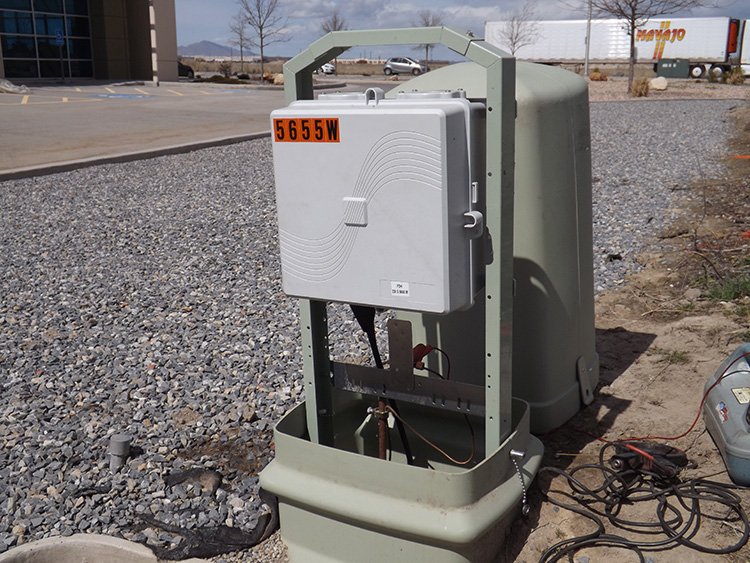
It helps to realize that since T1 was a product of the Bell System, there was only one type of T1 system ever produced. But DSL originated in the 1990s at which time there were several different major carriers and they each produced their own specific electronics, cabinets and terminology. This means that DSL cabinets do not all look alike. They come in a variety of appearances, however, there are only a few basic designs. The most distinctive are the CoolPeds which have a thin screen around the upper portion of the cabinet. Most of the other DSLAMs are a taller cabinet than CoolPeds, and have several protruding areas on the sides.
Many of the DSLAM’s are referred to by their brand name, such as the CoolPed by Emerson Electronics, or Next Level’s USAM (Universal Service Access Multiplexer). AT&T uses a DSLAM called ISAM, but their overall DSL architecture is known as U-Verse, and another DSL cabinet is called a VDSL-2. All of these are part of one of the many DSL systems.
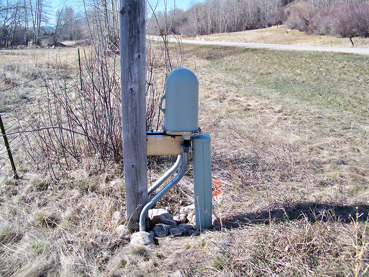
There are also some DSLAM’s that are produced in much smaller sizes than the standard cabinets. An example is the USAM-SSE (Universal Service Access Multiplexer-Single Shelf Enclosure), manufactured by Next Level Communications. This DSLAM cabinet is small enough to be attached to a utility pole, and can therefore connect into aerial phone cables.
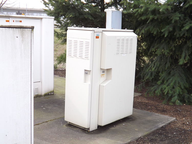
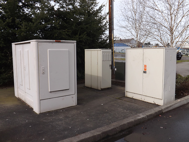
DSLAMs utilize a great deal of electronics so they are always energized. All repeaters and load coils are removed from the system when DSL is installed. T1 can not be altered to DSL, only POTS phone can be altered. Therefore, you can often see DSL cabinets and T1 cabinets side by side. This means that the T1 system is still functioning as normal, and the POTS system has been altered to DSL.
FIBER TO THE … – FTTx
Any communication system that uses fiber optic cable as a part of its architecture is an FTTx system. The first 3 letters stand for “Fiber To The…” The final letter denotes how close to the subscriber the fiber cable extends.
While DSL does provide greater bandwidth, it still can not compete with fiber optics. However, very importantly, the shorter the distance of the DSL line, the greater the bandwidth to the subscriber.
In other words, if there is a fiber optic cable that ends 8 blocks from your house, and then alters to DSL, then you should have very good bandwidth at your home. However, if that fiber cable extended just a little more and ended only 7 blocks from your house, then your bandwidth would be even better. It may not be a great deal better, but it would be better. The less phone cable in the system, the greater the bandwidth.
This has produced a number of different acronyms, and partially because different carriers are using different terminology. The only thing universal in this area in the communication industry is the basic FTTx indicator.
FTTB – FIBER TO THE BASEMENT
FTTB – FIBER TO THE BUILDING
FTTB – FIBER TO THE BUSINESS
FTTC – FIBER TO THE CABINET
FTTC – FIBER TO THE CURB
FTTH – FIBER TO THE HOME
FTTN – FIBER TO THE NEIGHBORHOOD
FTTN – FIBER TO THE NODE
FTTP – FIBER TO THE PREMISES
You can see that there is not a lot of clarity to many of these. Many of them are too similar to each other. Certainly, those such as FTTH, FTTB, and FTTP are indicators of a fiber cable that extends all the way to the home or business, and therefore there is no telephone at all in the system. It has all been replaced by fiber cable. All of the others indicate that the fiber is altered to telephone at some point before reaching the subscriber. This takes place at some type of fiber hut or node.
Any of these all-fiber systems run from the CO all the way to the subscriber’s house or business. That was very uncommon not many years ago, but it is growing rapidly. It is no longer possible to even state which parts of the country are the most likely to have FTTH or FTTB. There are already small towns in very remote areas that have FTTH, as well as suburban neighborhoods, and of course major urban areas across the country.
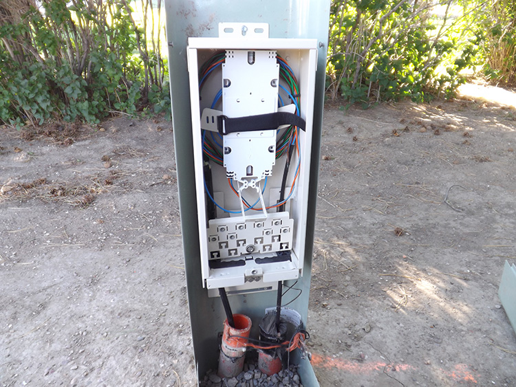
With any of these architectures, the alteration from fiber to telephone requires a communication node. This can be a sizable cabinet, often called a fiber hut. The fiber huts just like DSL cabinets are not all manufactured by the same company, so they do not all have the exact same appearance or name. Some of them are called a VRAD, which stands for Video Ready Access Device.
The closer the fiber is in to the neighborhood, the more likely the carrier is using only a much smaller device much like a Cable TV node and may fit within a telephone AP. These are likely only altering a single fiber strand to telephone.
All fiber huts, T1 cabinets, and DSL cabinets contain extensive electronics and must be energized, so they always have a power feed.
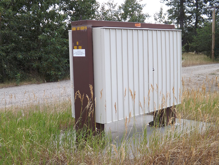
CONTROLLED ENVIRONMENT VAULT – CEV
POTS telephone plants were typically quite impervious to weather conditions, but that is not the case with T1, DSL, and FTTx. The new cabinets and their sensitive electronics do not stand up well to extreme cold, extreme heat, extreme humidity, and basically all the weather conditions which can be found in most parts of the country.
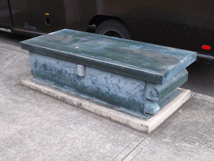
The temperature underground remains much more stable throughout the year than it does aboveground in any part of the world, so the answer was to drop those cabinets below ground. There still needs to be access to the cabinets for the telco technicians, so a feature known as a CEV (Controlled Environment Vault) was created to handle this situation.
From aboveground they appear as a smooth-topped metal structure, typically only about two feet high, and usually with vented panels on the sides. This is only the lid of the CEV which is itself completely contained underground. The telco technician uses a key to unlock the CEV, and since the cabinets already have an AC power supply, that electric power is also used to raise the lid up from the ground, expose the inside of the structure, where the technician can now step down inside the structure with full access to the electronics.
SUMMARY
Although these systems have been looked at individually, they are usually operating in conjunction with each other, especially with FTTx and DSL. Consider an imaginary scenario here.
You are living in a house that was constructed in 1965. All of the telephone cables from the Central Office 10 lineal miles away were placed the same year, as was the single pair telephone service to your house.
From the CO through the duct runs manhole after manhole, then out to the cross connect, pedestal after pedestal, as well as repeaters and load coils, and finally the service buried in your yard. It was all placed in 1965.
You still have that phone service to your house, but nothing else. But the Cable TV operator in the neighborhood is offering far more services than the Telco can. They have high-speed internet and Cable TV, and the cellular phone companies are taking away the last of your telephone business.
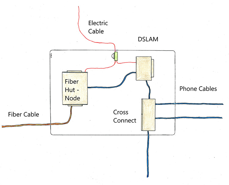
So, the Telco pushes fiber cable though empty conduits in the duct runs, and that old phone cable in the duct run is abandoned. The fiber cable now exits the duct run and connects in to a new fiber hut.
At the same place where the fiber hut is installed, there is also the first DSL cabinet. Between that point and your house, other DSLAMs are placed. Load coils and repeaters are removed, as well as some pedestals, and DSLAMs are installed.
Theoretically, not a single communication cable had to be trenched or bored into the ground at any point between the CO and your house. No open trenches or open pits, no diverted traffic or traffic control, no construction permits or traffic control permits, no trucks hauling in new cable or hauling out dirt. Even the old telephone service to your house did not need to be replaced.
There was no major excavation that ever took place. Yet now you have high-speed internet, Cable TV, and you still have telephone service as well, so now you decide to stick with the Telco for your communication needs. You now have 21st century communication. The telephone cable portion is now DSL, and the overall communication layout is Fiber To The Node – FTTN.
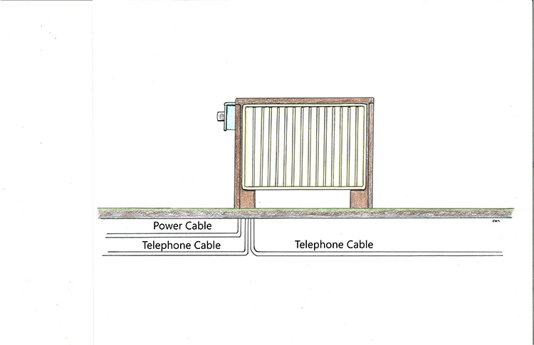
The only other important item here is the cross connect. All telephone cables must connect in with a cross connect cabinet, and almost always at the point where the cables come out of the duct run and run pedestal to pedestal. This is the crossover between feeder lines and distribution lines.