INDUSTRY TERMINOLOGY
The terminology included here is not specific to any type of utility, but relates to most or all different types of utilities.
ARCHITECTURE – TECHNOLOGY
Most utilities have their technology and their architecture – the electronic portion of the utility and the physical portion of the utility. A good example of this is the new 5G network. The change from 4G to 5G includes not only a change in the electronics and computer software (technology), but also includes the addition of small monopole transponders stationed at specific dead areas of reception (the architecture).
AS-BUILTS
An engineer’s drawing of the proposed horizontal and vertical placement of a utility line. Though the contractor agrees to place the utility as proposed, the reality is that there can be many unforeseen obstacles that force the contractor to alter the placement. This can lead to legal ramifications for engineers which is why the term “Record Drawings” is becoming a more preferred name by engineers.
BETTERMENT
Any work done on a utility line that includes an improvement to the utility is a betterment. If the gas company is simply moving the gas main to accommodate a change in the roadway, then there is no betterment. However, if the gas company is going to update the gas main from old iron pipe to poly pipe during the move, then that would be a betterment. The betterment may be paid by the utility owner, the municipality, or they may split the cost depending on the state laws and arrangements that have been made.
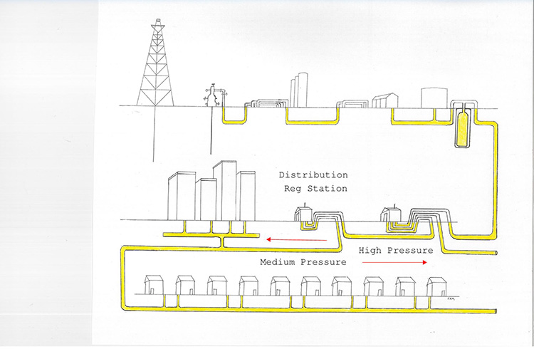
GATHERING – TRANSMISSION – DISTRIBUTION – SERVICE
All utility lines can be divided into one of four classifications. Gathering lines are found only with natural gas, petroleum, and water. The pipes connecting the gas well with the gas processing plant are gathering lines.
Transmission lines are high capacity utility lines meant to transport the utility to a distant area. Transmission power lines are usually easily recognizable because of the transmission towers. However, underground transmission power is becoming more common, with the primary cables inside of metal pipes, and in concrete ducts.
Many utility owners do not typically use the word “transmission” at all. Telephone transmission lines are referred to as feeder lines, or more specifically as duct runs. Feeder lines are also referenced in such diverse utilities as Cable TV and Storm Sewer. Transmission gas pipes are often called “high pressure”.
Distribution lines are the most common type of utility line in almost any utility plant. They may be called distribution, or main line, or mains. On almost any given street there will be a distribution gas pipe, telephone cable, water pipe, power cable, etc., and all running the length of the street.
Services are the line that connects the distribution line with the end user (house, office, cabinet, etc.). Service pipes are also called laterals, and service cables are commonly called drops.
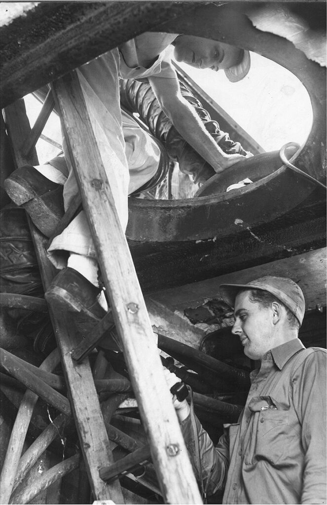
MANHOLE – HANDHOLE – PULLBOX
Manholes are belowground structures, usually at least six feet deep, and with an entrance opening smaller than the structure itself.
Handholes are belowground structures, usually no more than four feet deep, and with an opening that is as wide as the structure.
A Pullbox is a small underground structure, usually no more than a foot or so in length and less than a foot in depth. Pullboxes are used almost exclusively for traffic wires, street light wiring, and sprinkler/irrigation wiring. However, some utility owners may refer to their handholes as pullboxes.
The word “vault” is commonly used as well, though with an even more vague meaning. Some people use the word vault exclusively for underground electric structures, while others use it as a reference to either a manhole or handhole.
OSP – ISP
The operation of a utility is always divided into two separate systems, the Outside Plant and the Inside Plant. The distinction between the two includes not only the type of materials used, but type of features used and even the responsibilities of the employees. Utility employees work in either the OSP or ISP of the utility plant.
A good example of this is with telephone cables. Some phone technicians may work only with ISP, the phone cables inside the central office and the switching operations. But most phone techs work on the OSP portion of the plant with the duct runs, cross connects and pedestals.
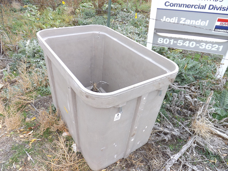
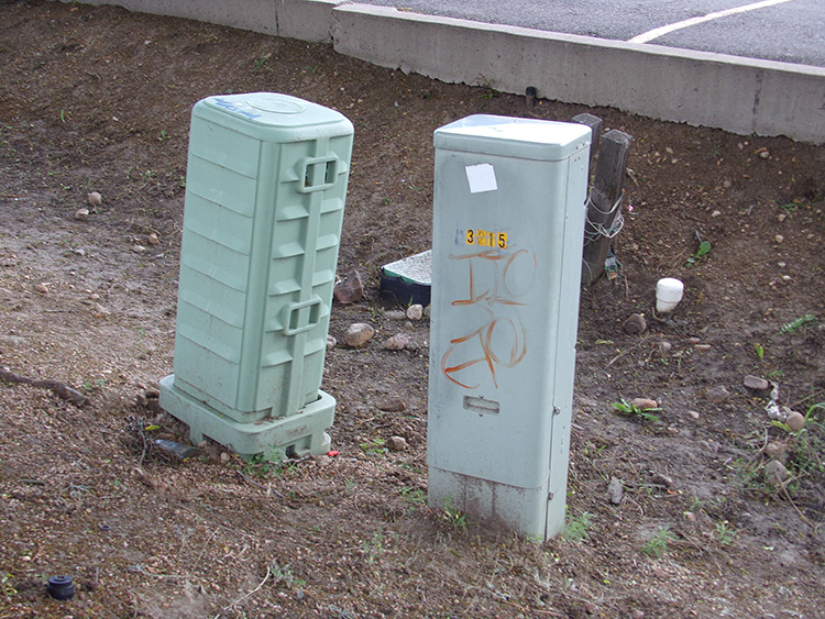
PEDESTAL
An above ground enclosure for cable connections, usually a non-energized enclosure. A telephone pedestal is not fed by electricity, but a telephone DSLAM is, and is therefore usually referred to as a cabinet.
PLANT
Utilities are of course not confined to a specific building. They function only because they spread out to thousands of different points. A utility plant is a reference to the entire utility operation and its physical system. Every power pole and every power cable on the pole is a part of the power company’s plant.
PUBLIC UTILITY – PRIVATE UTILITY
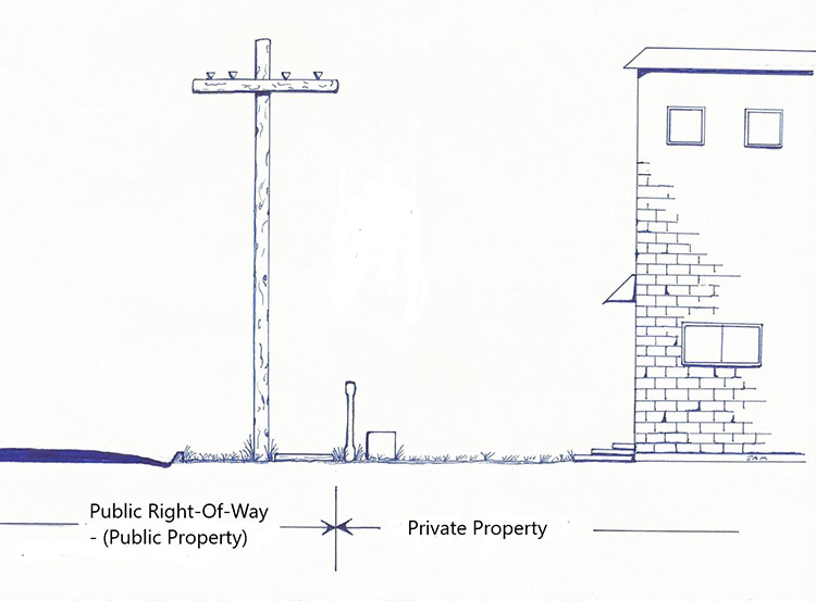
While the words “public utility” and “private utility” are commonly used, they can be somewhat vague, and sometimes used differently in different areas. The most common usage is probably the classification between the utilities which are placed in the public right of way (ROW) and feed various subscribers (residential or commercial), and those which are owned and contained on private property.
This does not mean that a public utility’s plant is entirely within the public right-of-way. The power meter to your house is almost certainly attached directly to the house. The same is usually true for the gas meter. The crossover point between ownership of a utility is never at the crossover point between private property and public property. For water, gas and electric, the utility operator owns the utility line to a point on the backside of the meter, and those are all within private property.
So, a public utility places its main lines within the ROW, but they also need to feed every building along the street, and that means the service lines must be placed, at least partially, within private property.
SUBSCRIBER
It may be common to refer to the user of a utility as a customer, but from the utility owner’s point of view, they are a subscriber. Like any other subscriber, they subscribe to the utility service.
UPSTREAM – DOWNSTREAM
Upstream and downstream are very obvious with storm and sanitary sewer. It is the flow of the water. However, with any other utility “upstream and downstream” refers to the flow of the utility service. With electric power the generating station is as far upstream as you can be, and the house or building is as far downstream as you can be.
UTILITY PRINTS – FACILITY RECORDS
All utility owners possess some type of utility records to document the details and extent of their plant. Many small towns often have nothing more than a large wall map with the water pipes drawn on to the paper. Larger utilities had book-like copies of the prints that could be taken out to the field. Some used microfiche records which could be difficult to read.
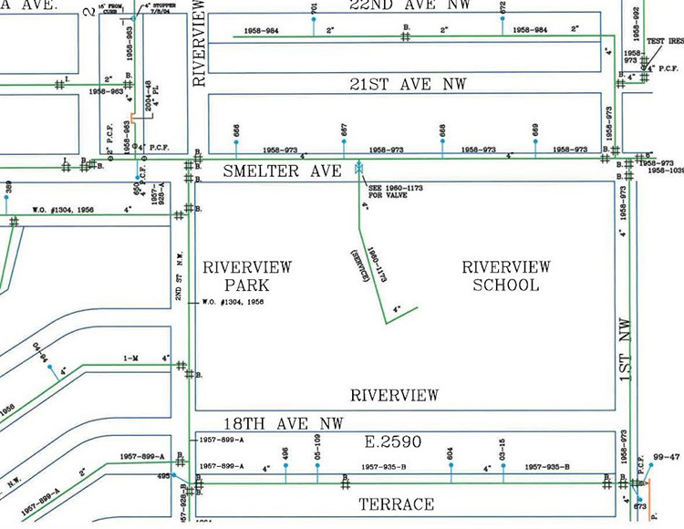
Today, most utility owners have graduated to computer records which can be updated better and easier. However, even the variety of computer prints can be very diverse.
Utility prints are not at all the same as as-builts. As-builts abide by engineering standards, including both horizontal and vertical measurements and using engineering symbology. They are also always drawn in black and white. As-builts must also be stamped by an engineer, a circular mark on the upper right of the page.
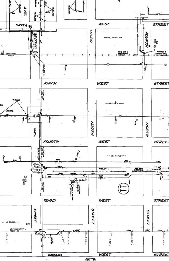
However, utility prints do not abide by any national or even state standard. They are strictly for the use of the utility owner and its employees and sometimes their contractors. They can be black and white or color (any color). They may use any type of symbology they decide. They are not stamped by an engineer.
Although utility prints for pipe utilities are usually intended as a map-type layout, cables are usually not. Cable utility owners often need to include far more information on connections, voltages, enclosures and other details depending on the type of cable utility. This leaves little room for drawing in a cable in a close proximity to where it was placed, or supposed to be placed. Therefore, cable utility prints can often be more of a schematic layout than a map. This is especially true with telephone cables.