Fiber Optic Cable
INTRODUCTION
Fiber optic cable is separated here as an individual utility. For long haul fiber companies, it certainly is a separate utility. Some cities even have their own fiber system. But at the same time, Telcos and Cable TV operators have installed a great deal of fiber, and even power companies today use fiber cable for communications using a specific type of fiber cable arrangement known as OPGW.
In 1976 Bell Laboratories announced that they were working on three innovative new technologies involving communication and communication storage. The three technologies were described as millimeter waveguide transmission pipe, magnetic bubble memory, and light pulses through glass.
The waveguide transmission pipe seems to have completely disappeared. The magnetic bubble memory actually came to fruition for a short period, and you can still find an old magnetic bubble memory cartridge for sale on eBay now and then, but it was quickly overshadowed by the original floppy discs. However, it was the third technology that literally changed the world, that “light pulses through glass” that we now call fiber optic cable.
The same year that the announcement was made, Bell Laboratories was already making their first full test at their lab in Norcross, Georgia, testing a fiber optic cable that could transmit 45 million digital bits per second. This cable was a polymer made of both glass and plastic, and the “light” is provided by lasers. Optical cables are limited in how much bend is allowed, but the combination of glass and plastic produced the flexibility of glass necessary to use light impulses as a communication medium.
In May 1977 the fiber cable that had already been installed in Chicago went on-line with telephone traffic. The next year the first fiber optic trade show was held in Boston, Massachusetts, and in 1980 the Winter Olympics in Lake Placid, New York made use of fiber optic cable for carrying video signals from the various cameras. By 1985 fiber cables were being placed all across North America.
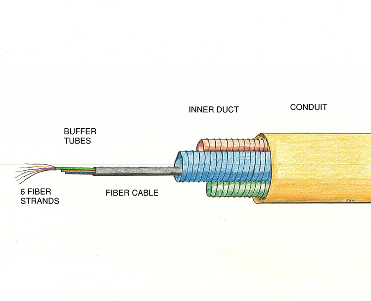
The individual optical fiber is known as a strand. Each strand consists of the core, the actual polymer of glass and plastic which carries the optical signal. The core is coated on the outside with an additional layer of the glass/plastic polymer to keep the light reflection inside. This coating, known as the cladding, allows “total internal reflection” so the light waves can travel over very great distances without a loss of signal. Each strand then receives a primary coating, which is a very ultra-thin colored plastic. The strand appears to be one single glass rod, but it is actually a glass core with glass coating and a primary coating.
All fiber cables are referred to by their strand count. The fiber strands are compiled in to a buffer tube with 6 strands per tube. The buffer tubes are also color coated, and all fiber cables consist of at least one buffer tube. The color coatings allow for specific identification of each individual strand within a cable, so a strand of fiber may be recognized as “the strand with white primary coating – in the blue buffer tube”. The buffer tubes are also protected by another layer of insulation, and usually several, and then the outside of the cable is made of polyethylene to protect against weather damage.
Since all fiber strands are combined with 6 strands per buffer tube, the minimum fiber count in a cable will be 6. However, a 6-strand fiber is typically only used as a service to a building. The majority of fiber cables are a 12 strand or larger, but all larger cables will have a strand count that can be divided by 6, such as a 12, 18, 24 strand, and so forth right up to the largest fiber optic cable, a 920 strand. However, the most common OSP fiber cables are 6, 12, 48, 96, 144, and 288 strand.
FIBER OPTIC CABLE CONSTRUCTION
There is an exception here for some of the larger communication firms. If XYZ Corporation wants a special fiber cable with only three strands per cable, or maybe five strands per bundle, they can not order it from a supplier the way anyone else would. But if XYZ Corporation is a large enough firm, and willing to pay extra, they can have it special ordered from a manufacturer.
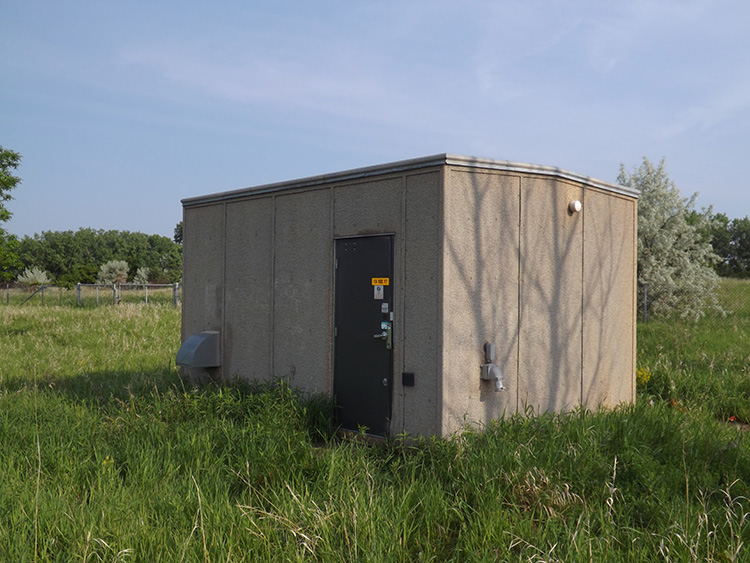
Fiber optic cables are produced in several different configurations, but almost all fiber used in outside plant is Single Mode Fiber. Originally single mode fiber optics had a maximum range of 66 miles. Today that range has been extended to near 90 miles. However, fiber is not usually placed in lengths more than 20 miles or so before being regenerated. The regenerating stations tend to look like a large group of storage sheds. These are often found in remote locations, but with security fences, cameras, and other protection.
To greatly simplify the technology, Single Mode fiber could be described as having a light beam that shoots straight through the fiber, while Multi Mode fiber bounces off the inner cladding. Multi Mode fiber is common for ISP, and is the type of fiber found in office buildings. Multi Mode fiber cannot be used over long distances without signal interference.
Most OSP fiber cable today has been upgraded to Wavelength Division Multiplexing (WDM). This is an additional technology to basic fiber that sends multiple frequency light pulsations. This is used on some ISP fiber as well.
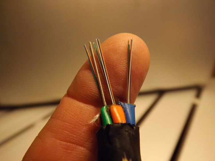
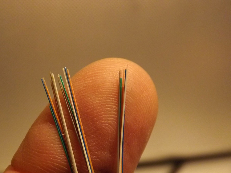
People are often surprised when they first see the size of a fiber cable. They may have heard about the extremely small size of fiber optics, but that is the core itself. Single mode fiber (OSP fiber) has an extremely small core, anywhere from 3 to 10 nanometers, so small that they can be difficult to see. However, once those cores are combined in to a buffer tube, multiple buffer tubes are combined together, and then insulated multiple times, and with the outer jacket, even the smallest fiber cables end up being about the same size as a coaxial cable.
The largest fiber cable, the 920 strand is about the same size as a 900 pair phone cable. Of course, it is not the overall size that counts, but the capacity of the cable. So, although fiber strands are only about the size of a human hair, some fiber cables can be larger than expected because of the abundance of insulation.
Besides the differences between single mode and multi mode fiber, there are also two main classifications of the outer jacket of the cable. Tight Tube (TT) fiber cable is just as it sounds, constructed with a very tight jacket around the fiber strand bundles. This is used almost exclusively for ISP fiber.
Loose tube (LT) cable is also well named. Pulling fiber cable through conduits can easily put too much stress on the fiber strands, so loose tube cable was created with a loose outer jacket that will slide over the inner cable to a certain degree if the cable is pulled tight.
So, although there are various types of fiber cable, almost all OSP fiber is Single Mode – Loose Tube.
It is not common for the single mode aspect of fiber cable to be identified obviously on the cable, or on the utility prints, but loose tube cable is very commonly identified as LT on both the prints and the cables.
FIBER CABLE IDENTIFICATION
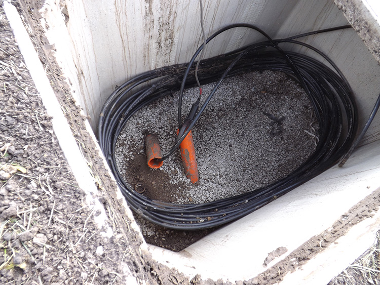
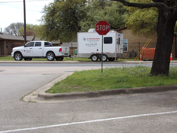
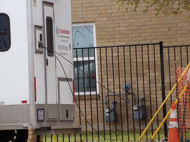
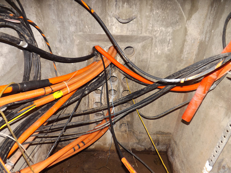
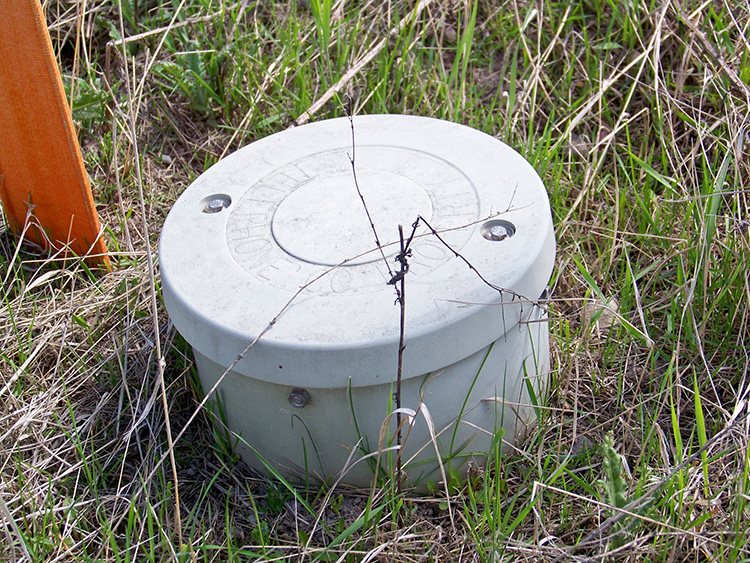
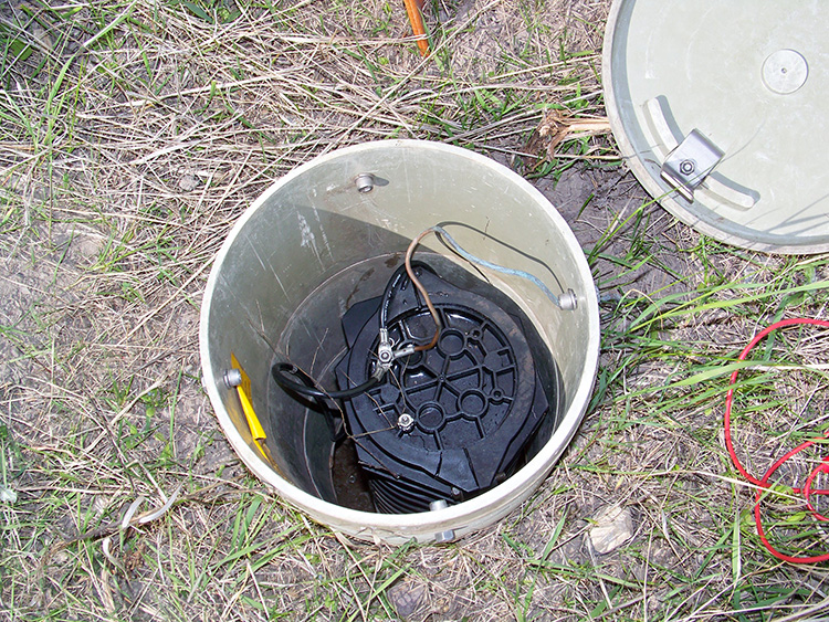
Fiber optic cables are identifiable in several different ways, and considering that almost all OSP fiber is loose tube and looks much the same as a small phone or coax cable, it is good to know what those identifiers are. Whenever a splice is made in the cable, the ends have to be pulled in to a fiber trailer or other specially constructed truck in order to be spliced. Unlike phone and coax, fiber optic cable cannot be spliced at a pedestal, or at the site of a cable damage. An optical cable must be spliced in an environmentally controlled room to prevent any dust or dirt particles from being on the fiber ends. Even a single dust particle on the end of the strand can prevent the optical signal from being operational. When fiber cable is installed, either aerially or underground, additional cable is always wound up in handholes, manholes, and on power poles. It is probably the most obvious sign of optical cable in a handhole, there is always a great deal of cable wound up inside the handhole to allow for the cable to be extended over to the fiber trailer.
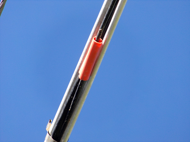
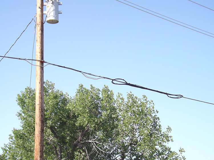
On a pole line fiber cables usually have orange bands attached to the cable. Aerial fiber also has continual loops, snow shoe loops, and for the same reason that handholes have loops. These wind the cable back and forth from pole to pole several times, and to ensure that each bend is not too extreme, the bends are placed in the plastic housings which look a lot like snow shoes. These are extremely common on fiber optic cables on pole lines, and have a very distinctive appearance. This is not a company procedure. It is a standard with fiber cable no matter whom the owner.
The abundance of fiber cable loops also allows for any fiber splice to be performed as a single splice. With fiber optic cable every splice has a very negative effect, and those splices need to be kept to a bare minimum. That extra fiber cable in manholes and attached to pole lines ensures that any splice is a single splice, not two splices when only one was needed.
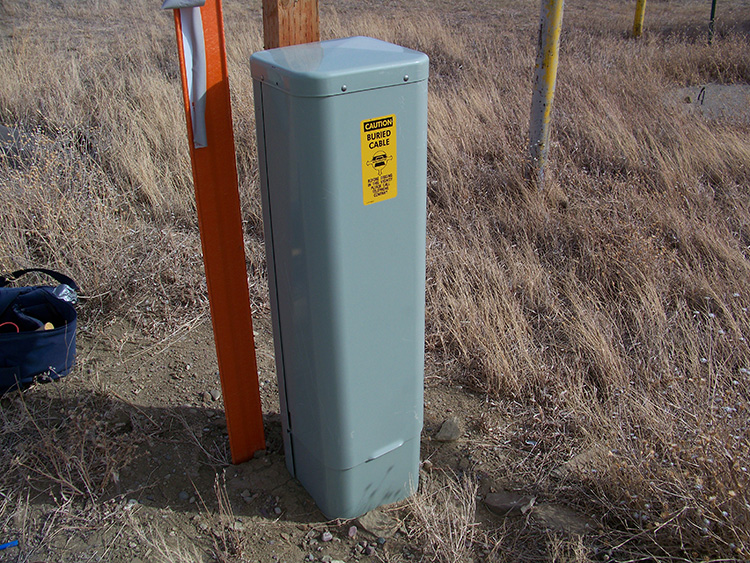
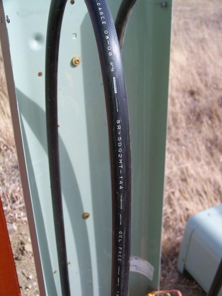
In some instances, fiber cable may be within the same pedestal as phone or coax. Optical cable can be identified by printing on the cable itself, but fiber manufacturers do not all use the same type of identification lettering. Some manufacturers do not print much more than the word “optical cable” on the outer jacket.
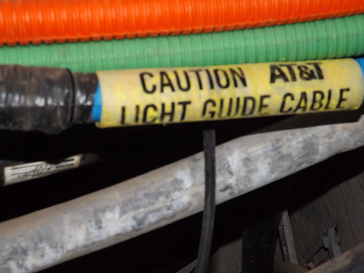
As previously stated, the acronym LT is very common on fiber codes, and identifies the cable as loose tube. Another common acronym is LG which stands for Light Guided, a common name for fiber optic cable in the 1980’s. That term is no longer in popular usage, but the acronym LG is still commonly found printed on old fiber cable. Those lettered codes are usually included as part of the overall code for the cable, which would also include the strand count. A code on the jacket that is labeled “LG – 24”, would represent “light guided cable – 24 strand”. A common longer code may be “PC – 3412LT – 144”. In this case the LT acronym is used for loose tube, but the strand count, 144, is still the final portion of the code. The easiest way to remember this is by the two main acronyms, LG and LT, and that the strand count is almost always the final number of the code.
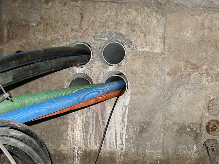
Fiber cables are often first placed inside of inner duct. This is a plastic tube which is commonly manufactured in a corrugated form, so they have a very rippled appearance. The purpose of inner duct is to protect the cable from being pulled too harshly as it is pulled through the conduit. Although fiber cable can be damaged from being bent at too harsh of an angle, the biggest danger to fiber is from being pulled too hard which may pull the actual fiber strands. The fiber strands can not be stretched at all. This will only cause the fiber strands to snap.
These corrugated inner ducts are typically in a combination of three bright colors: red, green, and blue. The smooth surfaced inner ducts are usually in a color combination as well, often with one bright orange inner duct, and two darker colors. Just like the color coding of the outer jacket of each fiber strand, the different colors of inner duct can be used to identify different owners of multiple fiber cables in the same fiber run – “We own the blue, you own the orange”.
Most communication conduits are either 3.5” or 4”, and either one can hold 3 inner ducts snugly. Inner-duct can be either smooth sided, or corrugated. The corrugated inner-duct is more lightweight and more elastic, but smooth sided inner-duct has twice the tensile strength, 600 for corrugated and 1200 for smooth wall. The conduit serves as the true protection for the cables, while the inner ducts make it easier to pull the cable through the conduit without putting too much pressure on the cable, and to keep the fiber cables more evenly spaced so that pulling on one cable, does not pull the others.
CONDUCTORS & TRACERS
Fiber optic is the only type of utility cable which does not require a conductor to function. All power, telephone, coaxial, street light, and traffic cable is conductive by necessity. But fiber cable can be completely non-conductive and still function as normal. In fact, most aerial fiber is non-conductive.
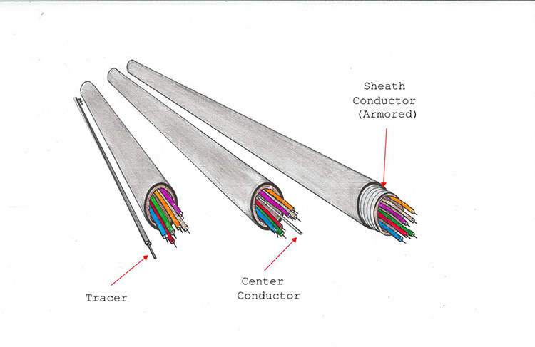
However, for buried fiber cable that leaves the problem of locating. Like any other utility fiber cables must be located out and marked before excavation to prevent being damaged. Therefore, there are three basic options used to ensure that buried fiber is locatable: armored fiber, fiber with a center conductor, and various types of tracer wire.
Many fiber cables are armored, having a metallic sheath just inside the outer jacket. These are often corrugated steel much like the sheath of telephone cables. Although this type of fiber is usually called “armored cable” it is hardly an armor. It would be more accurately described as metallic sheathed cable. However, this can help in preventing rodent damage to the cable.
Some fiber cable will have a center conductor. This of course does not prevent rodent damage, but only serves to give the cable a more rigid backbone for aerial cables, and provides locating capability for buried cable.
The third option is tracer wire, but that tracer material can be in a wide variety of forms. That “tracer wire” may be a small common insulated wire, a thick insulated wire, a ground wire, or even a CRW which is actually a stiff 2-wire telephone service wire. The “RW” actually stands for “Rural Wire” because these phone services were originally manufactured for use as a durable rural telephone service. These are often indicated on utility prints with the notation “CRW placed for locating purposes”. In some cases the modern phone services are even used as a tracer.
One type of tracer does not even look like tracer wire of any kind. In fact it is commonly known as mule tape. This is a cloth-type of material which is regularly used to pull cables through conduit. Mule tape is commonly found in empty conduits, already pulled through, and now in place for when an actual cable is ready to be pulled through the conduit. Some mule tape is manufactured with a thin inner conductor for locating purposes. This is the smallest tracer ever used, so it does not stand out easily, but since the tape is a fiber/cloth material, it only takes running a finger across the end of the tape to feel for a conductor.
Another option for tracer is a conduit called toneable duct or tracer wire inner duct. Though this is as good of an arrangement as any other conductor placement, it is rarely used.
PEST DUCT
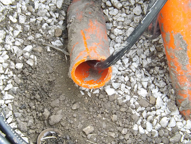
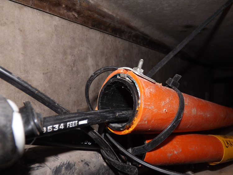
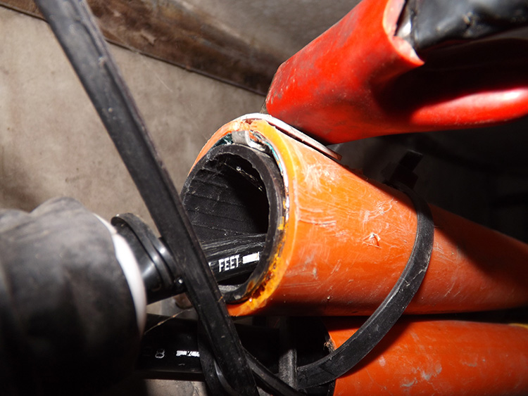
The more common conductive conduit is pest duct. Just as it sounds, this is designed to prevent rodent damage. The outer portion of pest duct is always orange like many other conduits, but it also has a black interior which can usually be seen at the end of the conduit. In between the outer orange and inner black plastic layers is a metallic sheath made of thin steel. Gophers often chew their way through plastic conduit, but they don’t chew through steel, even thin steel. Pest duct is often named for the brand of conduit such as Tamaqua, which is a manufacturer of pest duct.
Therefore, pest duct serves two important purposes. It protects the fiber cable from rodent damage, and it contains a solid conductive path from handhole to handhole to ensure the fiber can be located out before any nearby excavation.
OPTICAL GROUND WIRE (OPGW)
Another development in fiber cables is the Optical Ground Wire – OPGW, also known as FOG for Fiber Optic Ground. These cables are always owned by a power company, not a fiber operator. Their purpose is to provide fiber communications from sub-station to sub-station. This is not conversation communications, but signaling taking place to switch gears and other features.
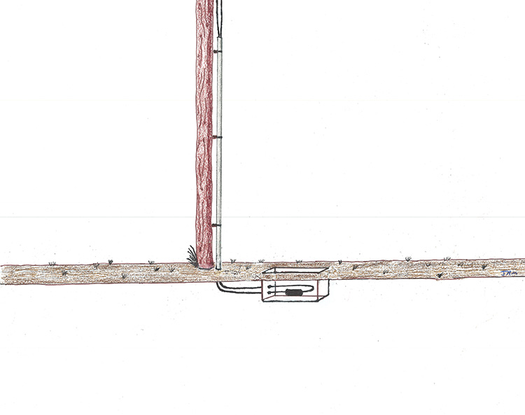
Transmission poles have a top ground cable, the highest cable on the poles, known as the static wire. These are made of aluminum, and are there to provide a path to ground during any electrical storms. So, the idea was actually quite simple: take an un-armored fiber cable and wrap it in aluminum, then use it for the static wire. You now have two utilities in one.
The fiber will usually come half way up a pole, or transmission tower, then go in to a splice case. The cable coming out of the other end of the splice case will be un-armored fiber, but wrapped in aluminum. This makes Optical Ground Wires very easy to spot, that typical looped fiber cable, only hanging on a power pole or tower, and with an aluminum covered cable going up the pole.
Additional information on fiber cable can be found on the pages TELEPHONE: T1 – DSL – FTTx, and TRAFFIC: ATMS
TERMINOLOGY
INNER DUCT
A brightly colored plastic tubing placed inside of conduits in groups of three. Used only for fiber optic cable to prevent excess pressure from being pulled through the conduit. Fiber Optic cable is most easily damaged by being pulled, not from being bent.
LG (LIGHT GUIDED)
An early term for fiber optics. No longer in popular usage, but many older fiber cables and prints still include this acronym.
LMS (LINE MANAGEMENT SYSTEM)
A system of applying a locating current on to fiber optic cables (tracer or armored) from a remote transmitter at a CO. Commonly used by long distance providers.
LT (LOOSE TUBE)
A fiber optic cable with a loose outer jacket to help prevent damage from tension on the cable. Almost all OSP fiber cable is single mode – loose tube.
MUX cabinet
A multiplexing cabinet, typically an ISP structure fed by a fiber line. In a large office building that is fed by a fiber cable, somewhere inside the building there will be a MUX cabinet that transfers the communications from that single fiber line to various LAN lines.
OPGW (OPTICAL GROUND WIRE)
A fiber cable built in to a power line static wire, and owned by the power company.
PEST DUCT
A conduit with an inner metallic sheath, used for fiber optic cable. Pest duct is usually orange or orange/brown on the outside, and black on the inner layer. The metallic sheath is contained between the two layers. Sometimes referred to by the manufacturers name of Tamaqua.
SNOW SHOE
A tear-dropped shaped plastic cable holder, lashed to cables between power poles, and used to loop fiber cable back and forth along the pole line.
STRAND
The actual optical glass/plastic communication portion of a fiber optic cable. Difficult to see with the naked eye, all strands are color coated, and manufactured with 6 strands per buffer tube. All fiber cables are referred to by their strand count.