NATURAL GAS
INTRODUCTION
Just like coal, both oil and natural gas are called “fossil fuels”. This originates with the scientific theory that oil, gas, and coal are created by the decay of living matter. It is the decay of all living organisms that is considered to be the origination of petroleum. Landslides, earthquakes, volcanoes, and other earth movements have trapped large deposits of plant and animal life under the earth’s surface where the heat and pressure from above then break down the organisms into a basic form. This process of course takes millions of years. Whether the organisms turn to a solid (coal), a liquid (oil), or a gas (natural gas) can be from a variety of possibilities. However, this theory is being debated more and more.
One of the main differences between oil and natural gas, and the most obvious one, is that at room temperature oil is in a liquid form, while natural gas is typically in a gaseous form. However, this is not always true. Propane is actually natural gas in liquid form.Natural gas is a light hydrocarbon gas, therefore it is made of hydrogen and carbon. It is a mixture of several different gases, mainly methane, and methane makes up 85% to 90% of natural gas today. The various other properties of gas depend on the particular gas well that supplied the resource.
PLANT LAYOUT
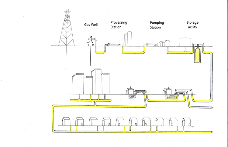
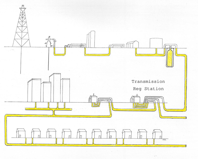
Most types of utilities can be generated from any starting point. That is to say, if we wanted to build a telephone system, we could construct our first CO (Central Office) anywhere in America, and then construct the distribution lines outward from there. Since petroleum is a resource, the petroleum lines will originate in the areas of the country where this resource is found.
Transmission lines are often called “high pressure” for the amount of pressurized gas the lines carry. Transmission lines may be on a major street, running through a residential neighborhood, or through a farmer’s field. Gas transmission pipes are always made of steel. The modern lines also have a fairly heavy coating that is wrapped around the pipes to help protect against corrosion. Once uncovered, transmission gas lines may look black or gray, depending on the wrap or coating material.
PIPE PRESSURE
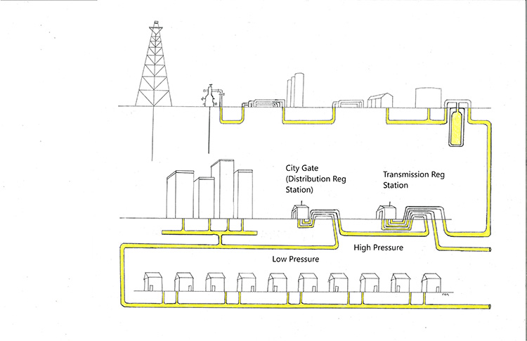
Natural gas pipes can be set to operate at a diverse range of pressures, all except service lines. According to the American Gas Association, transmission lines can be operating at anywhere from 200 to 1500 psi. Distribution lines can be anywhere from 0.25 to 200 psi, but gas services are typically operating at 0.25 psi.
GAS CASINGS
Casings are not strictly for gas lines, but you will find that both gas and petroleum operators use casings more than any other utility. Throughout the 1980’s and 90’s they were mandatory in many situations, but there were a lot of gas operators who felt that they did more harm than good. This is still a very debated point, and casings are still mandatory in some States, but the federal government has dropped it’s mandatory requirement for their use, and now goes with suggested requirements.
Casings are not strictly for gas lines, but you will find that both gas and petroleum operators use casings more than any other utility. Throughout the 1980’s and 90’s they were mandatory in many situations, but there were a lot of gas operators who felt that they did more harm than good. This is still a very debated point, and casings are still mandatory in some States, but the federal government has dropped it’s mandatory requirement for their use, and now goes with suggested requirements.
PIPE MATERIAL
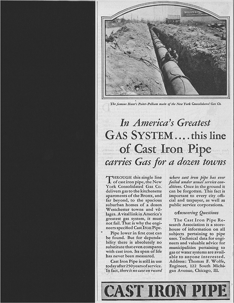
Gas pipes were all made of cast iron for almost a hundred years beginning in the early 1800’s. This was at a time when natural gas was used primarily for street lighting in the cities. Each street light had to be turned on at its valve, and then light every evening which was an occupation all its own at that time.
Just like pressurized water, natural gas first became common not as a service provided to homes, but as an important element to urban life. Water was needed to fight fires, and gas was needed to light up the city before electric power became available. The residential use would only gradually become popular.
Steel pipe began to replace cast iron by the early 20th century, and yet plastic pipe came along not much later. The first set of standards for plastic gas lines were not established until 1963. These standards dealt with the manufacturing of plastic for gas distribution. They were completely voluntary standards, though they became a little more stringent in 1967. In 1965 there were only about 9000 miles of plastic gas lines in the U.S., but more than 45,000 miles of plastic by 1970.
The first plastic gas pipes used a tan colored resin in their manufacture so the pipes are actually a tan color, and these first plastic gas pipes began to develop a rather shady reputation. There were three different manufacturers of plastic for gas lines up to the 1970’s. One of these companies received a lot of attention in later years because of structural problems in plastic at the tap connections. Amdevco, a division of Union Carbide, produced gas lines from 1970 to 1979, at which time they went out of business. A large number of serious disasters had resulted in extensive property damage and quite a number of deaths. Amdevco had been producing their pipe from DHDA Tan Resin, and in 1996 the National Transportation Safety Board began an investigation in to whether or not this material was responsible for the accidents.
The investigation concluded that all of the Tan Resin products were to some degree susceptible to cracking, especially at the tap connections. This was compounded by a lack of established procedure in installing the taps to prevent undue stress on the pipe. The tap connection had to be installed with a strong support material under the tap, otherwise the 3-way tap connection could easily be cracked by aboveground pressure. The problem was considered to cover basically all plastic pipe installed up to the early 1980’s. It was not a conclusion that all plastic from that era was dangerous, but that any plastic up to the early 1980’s that had not been carefully installed could be dangerous. By the time the investigation had even begun there had already been improvements not only in the resin production, but also in operating procedures.
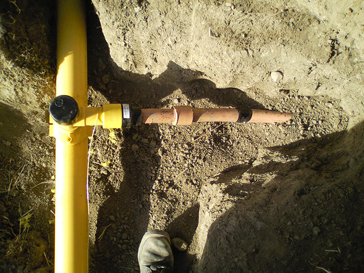
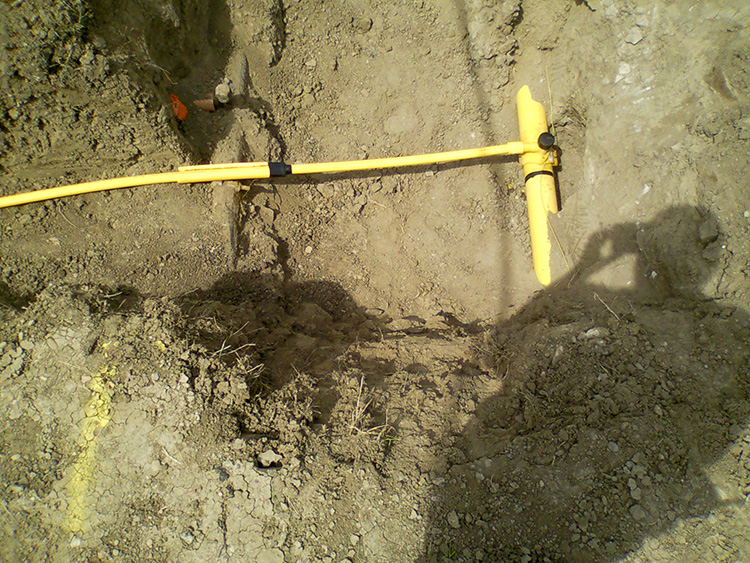
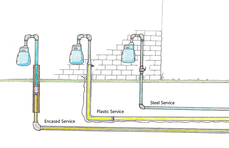
Today when plastic gas pipe is uncovered it is easy to see the difference between the old and new pipe. Tan resin has a washed-out coloring which may look somewhat tannish in color or even a washed-out milky-orange, depending on the manufacturer of the pipe. The newer pipe is a bright yellow resin. There is still a good deal of old cast iron gas pipe still in use, typically only in the region east of the Mississippi River. Steel pipe is still being installed in limited amounts, mainly for high pressure gas, but 95% of all new distribution and service gas pipes are poly pipe.
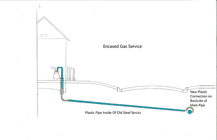
Typically, there were 2 other changes that would be made. The old steel tap could easily be capped off, but you could not connect a new plastic service into the old steel tap area. This meant tapping into the distribution pipe in a different location, usually a few feet away, and sometime even on the other side of the steel main. So, the plastic line will cross over the steel main, before connecting. It was also common to replace the old gas meter with a new one, and also quite common to move the meter to a different location on the building
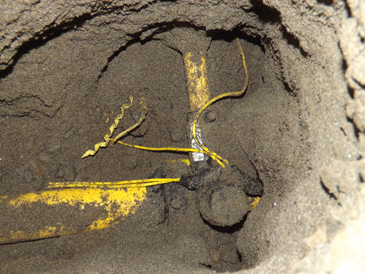
One drawback to this procedure was that since the plastic pipe would have to be smaller than the steel line it was replacing, they would need to use the largest possible plastic that could fit into the old steel line. Typically, this would be a ½” plastic being inserted into a ¾” steel. The amount of gas that could run through the pipe was now lessened, but not by a great deal. However, it never left room in the pipe to insert a tracer wire. The drawback to encased services is that they almost never have a tracer wire for locating, and since the steel portion of the line is not connected all the way through, connecting onto the riser will usually not provide a direct connection either.
Encased services are sometimes identified on prints as ENC for encased, or CSG for casing.
URBAN SERVICES
All gas services must be constructed so that the service can be shut off from outside the building. On a typical residential building it is easy to see the shut off valve on the riser. In very urban areas it may seem that this is not true because the entire riser/meter apparatus is usually inside the building. However, the standards are still in existence, just not at all as noticeable.
Urban gas services have two main configurations. One possibility is the gas service shut off being accessible from outside the building on a small elbow portion of the pipe. Though only a short portion of the pipe is visible, this will contain the shut off valve.
The other possibility is a configuration where none of the pipe is visible from outside the building. The pipe goes directly into building, then comes up to the meter. In this case there is a very small portion of the pipe that actually is accessible, but just not visible. There will typically be a small valve cover box about a foot or two out from the building. This cover allows access by the gas technicians to turn off the gas service from outside the building because the shut off valve is directly below the cover.
REGULATOR STATION – aka REG STATION – CITY GATE – GATE STATION
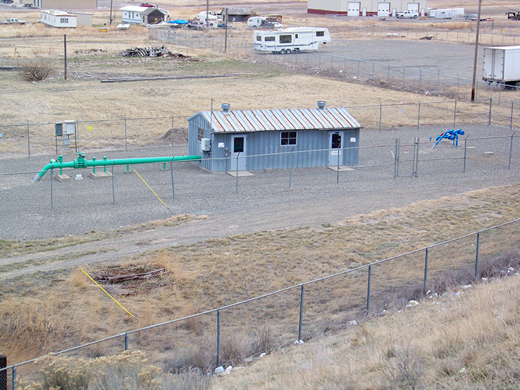
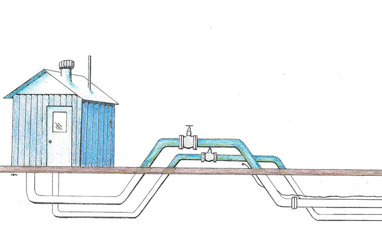
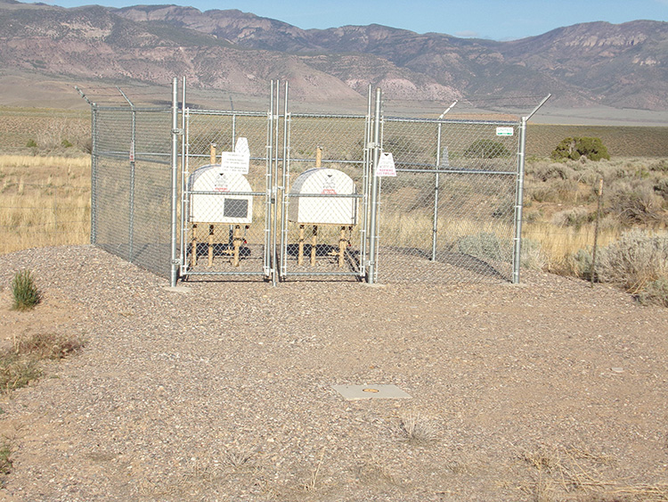
Every transmission pipe will eventually drop down to a distribution main. Instead of simply tapping into a transmission main (as an in-line regulator would do), the transmission line will come to an end, and now feed directly into a regular gas main. This will all be situated above ground so that the maintenance crews have full access to the structure. A reg. station can be only 10 feet across, or possibly up to 100 feet or more. It all depends on how many pipes will be configured here, and sometimes how much property the gas company owns at that position, which brings up an important point. Most gas lines, like most other utility lines will be constructed in public ROW’s or within utility easements, but regulator stations will only be within property owned by the gas company. They are going to be within a fenced area with a locked gate, and are a limited access area.
All regulator stations will have a similar layout. If there are just two pipes, transmission and distribution, then they will be laid in a parallel fashion, side by side, into the shed, where the two pipes will actually connect, along with a blow-off apparatus in case of excessive pressure. These are a very recognizable structure, two pipes coming above ground, side by side, then going back underground, and in close proximity to a small shed.
The transmission pipe has higher pressure partially because it is a smaller pipe. The smaller the pipe, the higher the pressure from the same source. Therefore, at reg stations, the smaller pipe is going to be the transmission pipe, the larger pipe will be the distribution pipe.
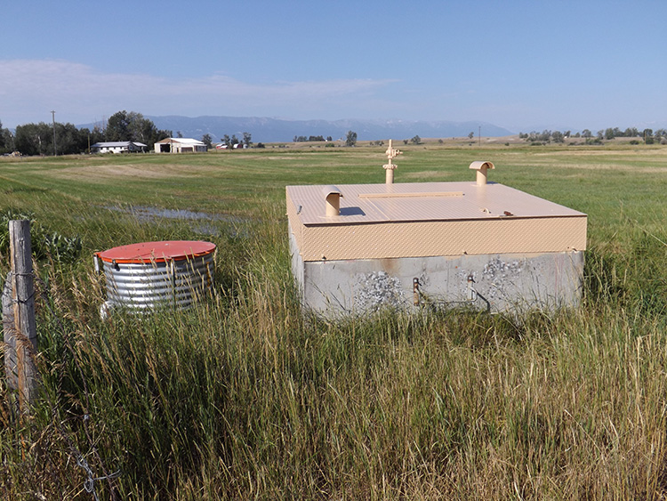
HIGH PRESSURE TAP
A High Pressure Tap is an apparatus that serves as the connection between a transmission pipe and a distribution main that feeds only a few buildings, or it may feed only a single gas service in a very rural area.
If the gas company installed a transmission pipe along an open field twenty years ago, and now that area is being turned into a new subdivision, they can tap into the transmission line with a small pipe which helps cut down the pressure slightly, then comes up to an enclosure, then back in to the ground, where it can now feed a regular gas main, even a plastic main, at a more normal operating pressure. These HP Taps can be made in a variety of configurations. They are sometimes referred to by their shape: a birdcage tap does look very similar to an old birdcage, and a milk-can tap looks somewhat similar to an old upside-down 19th Century milk can.
NATURAL GAS TERMINOLOGY
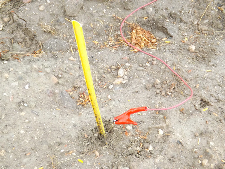
DEAD END MARKER
Most utilities will have occasional dead ends, however on gas lines, especially with the newer plastic gas mains, it is common for some gas operators to place a thin plastic marker at the dead end. The bottom of these dead end markers may be buried right at the end of the gas line, and with the tracer coming above ground, wrapped around the marker. This makes locating the dead end much easier. These markers are very flexible, so construction activity may have buried the top of the marker as well, but usually only a few inches under the soil.
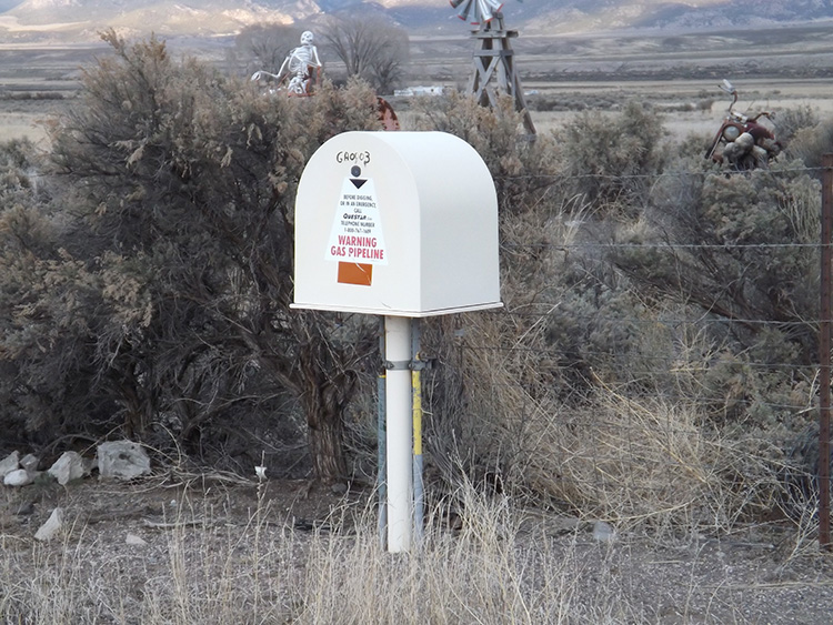
FARM TAP
A High pressure Tap for tapping into a transmission/high pressure gas line to provide gas service to one or two farm houses. They are common in very rural areas where there is a nearby transmission line.
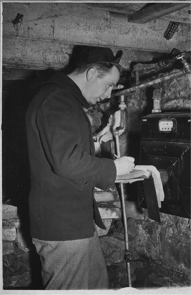
GAS METER
The actual meter which registers the amount of gas being used at the building. Gas meters are attached to the top of the gas riser, the pipe that comes up from the ground. A gas meter may, or may not, be directly attached to the building it services. In urban areas the meter may be inside of the building.
FARM TAP
A High pressure Tap for tapping into a transmission/high pressure gas line to provide gas service to one or two farm houses. They are common in very rural areas where there is a nearby transmission line.
GAS METER
The actual meter which registers the amount of gas being used at the building. Gas meters are attached to the top of the gas riser, the pipe that comes up from the ground. A gas meter may, or may not, be directly attached to the building it services. In urban areas the meter may be inside of the building.
REDUCER – RED
Connection for reducing a larger pipe into a smaller one. Such as a 4-inch gas main reduced to a 2-inch.
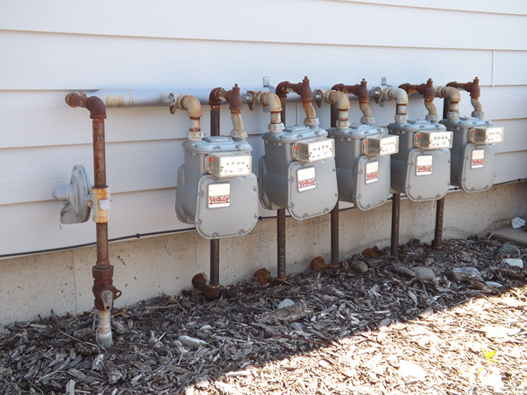
RISER
A riser is a term used to describe the portion of a gas pipe that comes up out of the ground, and then connects with the meter on the side of the building. The shut-off valve is usually positioned on the riser about a foot above the ground. On a regular sized house, the riser is the only physical support for the meter. On a larger building, or a building with multiple gas meters coming off of one riser, there will also be additional metal pipe into the ground to hold up the meters.
SERVICE LINE CARD – SERVICE CARD
Because of the delicate nature of gas, gas operators have almost always insured that each gas service is measured after it is installed, but before the trench is covered up. This allowed the gas line to be located by measurements if necessary. The measurements were written out in the field on a sheet of paper, then filed in the office. These are often kept separate from gas prints since the number of measurements would be too massive to include on the prints. If a technician needed these measurements, they could request one from the office by referring to the service line number, such as “SL7823112”.
SERVICE LINE
Any line that connects into a building, whether it is a residential dwelling, or a large commercial building, is a service line. Service lines can be in a wide variety of sizes. For a house, a gas service will usually be a ¾ inch. The gas service into a large sports arena may be a 4-inch pipe.
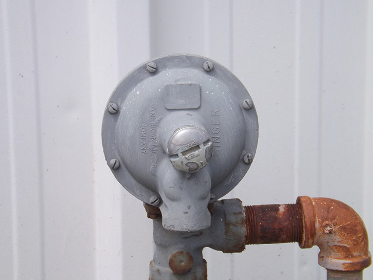
SERVICE REGULATOR
A service regulator is just as it sounds, attached to the gas service. They are a round disc shape, about 6 inches in diameter. Only some gas services will have a service regulator, it strictly depends on the exact pressure of the gas main that is feeding the service.
Some gas services will have only a regulator, not a meter. This tells us that the gas line is private, because the meter must be farther away from the building.
SHUT-OFF VALVE
Every gas service must have a shut-off valve attached to the pipe which can be used to cut off the gas entering the building during an emergency. A shut-off valve must always be accessible outside the building. Typically, they are on the riser outside the building, but in an urban area where the meters are on the inside of the building, the shut-off valve will still be outside the building.
TAP or T
A 3-way connection between any two pipes, such as a distribution pipe and a service pipe.
TRANSITION FITTING – TF
A fixture that connects two pipes together of different materials. For gas pipes this would almost always be a connector between steel and poly pipe.