CATHODIC PROTECTION
One of the important things to understand about Cathodic Protection is that it does not prevent corrosion. That is impossible. The purpose of Cathodic Protection is to divert corrosion to a point away from the pipes.
Many natural gas distribution pipes are made of steel, all high pressure (transmission) natural gas pipes are made of steel, and petroleum pipes are usually either steel or steel cylinder in concrete. There are also a number of very old iron gas pipes still in service in the Eastern U.S. Corroded metal water pipes can be hazardous, but not as hazardous as metal gas pipes. What all of this comes down to is that Cathodic Protection is mandatory on metal gas pipes, most of which are steel.
There are two basic types of CP, one used on gas distribution pipes, and the other used mainly on petroleum pipelines.
Understanding CP begins with understanding corrosion, or more technically, electrolysis. Technically, electrolysis is “the decomposition of a substance by the passage of current flow from metal to soil”.
Anytime we bury a metal pipe in the ground, the electrolysis will be inevitable. Ferrous metal (iron and steel) is the most easily magnetized metal, and will have a higher reaction with the surrounding soil than any other types of metal such as aluminum or lead. Simply put: iron and steel have rapid corrosion rates, and they will take any pathway to returning to their natural state of iron ore.
How severe the corrosion will be is relative to any coating or wrapping on the pipe, and very much on the type of soil. Sandy soil will create only a mild electrolysis, while clay soil (wet soil), will have a very high electrolysis. Either way, electrolysis will occur, and unless the pipe is protected somehow, it will begin a gradual process of returning to its natural state of iron ore. Therefore, the purpose of CP is to divert that electrolysis to a specific point away from the pipe itself.
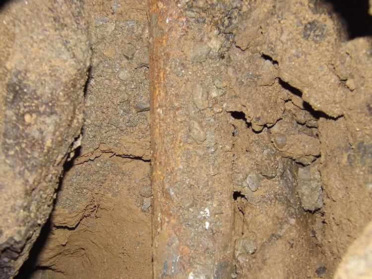
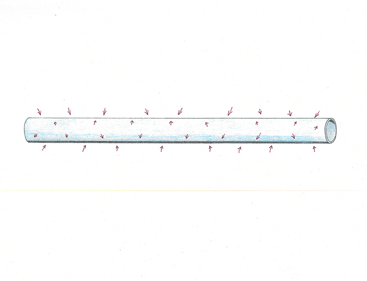
Let’s look at how this occurs. We have a steel pipe buried in the ground, no coating, no CP of any kind, just a steel pipe in the soil. Electrolysis will be occurring all along the pipe. There is stray current being attracted to the pipe, and that current is also exiting the pipe, and this electrolysis is occurring all up and down the pipe.
A very important point is that current being attracted to the pipe does not cause any corrosion of any kind. Electrolysis (corrosion) occurs only where current exits a conductor. It is impossible to tell the difference when looking at the pipe. There is corrosion everywhere, so it seems as though it is all one phenomenon, but that is not the case. The attracted current is not causing any damage. Only the exiting current is, but current is entering and exiting the conductor throughout its entire length, so we do not notice that.
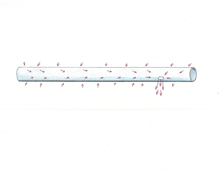
If we were to scrape all of the corrosion at one specific point, then we could more clearly see what is happening. It would not undo the corrosion that had already occurred, but all future exiting current would be taking place at that single point of bare steel.
We have created a specific anode at that bare metal, an anode being any point where current exits a conductor. Previously the entire pipe was functioning as both a cathode (current entering the conductor) and an anode (current exiting the conductor). The entire pipe is still functioning as a cathode – but now only that bare portion of steel is the anode.
We have not prevented corrosion in any way – but we have directed it to a single bare section of the steel. Of course, now that bare steel – that anode – will corrode very rapidly, but while it does, the rest of the pipe will no longer experience any corrosion. Yet, all we really did was to focus the corrosion onto a single point of the pipe.
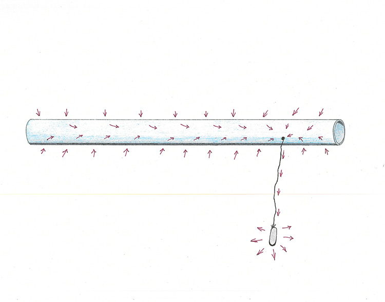
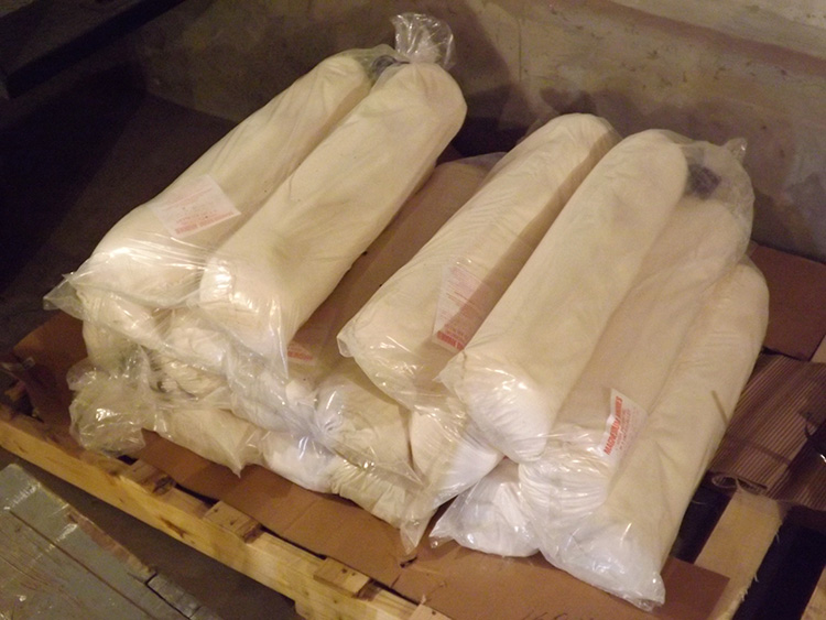
There is however, something else we can do that will be much more useful. Instead of scraping a single point on the pipe, we attach an insulated wire to the pipe – and run that wire a distance from the pipe – then attach a material to the end of the wire that is more reactive with the soil than ferrous metal – such as magnesium or zinc. Now all of the current will exit at this bag of magnesium – and remember – current only causes corrosion at the point of exit.
The simplest and least expensive type of CP is Galvanic Anode CP (GACP), and this is how it functions. Attach sacrificial anodes to draw the current off the pipe. The anodes will corrode very fast, lasting maybe only a few years, but during that time the pipes will not experience any serious corrosion.
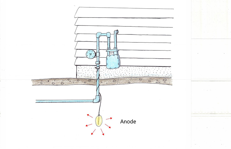
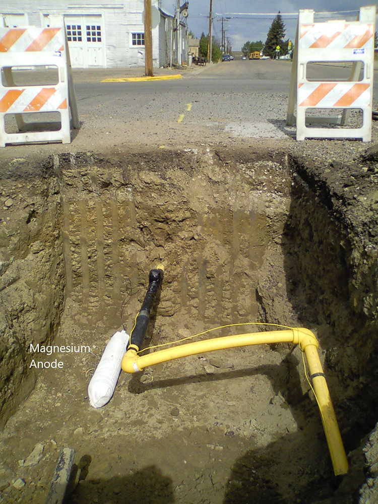
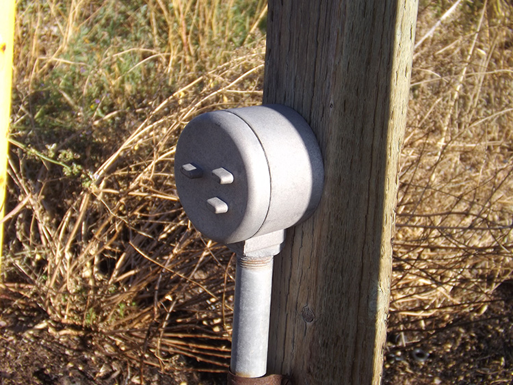
These sacrificial anodes may be attached at a gas riser, and buried below the riser. The wire from the anode will almost always have a thick black insulation, and the top of the wire will be attached to the riser with a wire clamp.
Sometimes a gas operator may decide to cover a fairly large area of steel pipe with a single group of anodes. In this case they will place multiple anodes together in an anode bed.
All of these practices are GACP, using simple anodes. However, GACP can not produce enough current pull to cover a large area, or to be effective on very long stretches of pipe. That is the reason for pipeline operators using Impressed Current CP (ICCP).
With ICCP the same basic principles all apply. The only real difference is that now electrical current is added into the system. Instead of relying on the natural flow of current to a reactive material, now electrical current is added to the system to “push” the current.
The problem here is of course that electrical current is AC, alternating current, so it shifts back and forth. That would only defeat the purpose of the system, so a rectifier is used to change the AC to DC. Now the current can only move in one direction – down on to the anode.
Of course, in order to push the current, that current would need to be applied out to the ends of the pipes. That actually becomes a natural event because all current moves in a circuit. In other words – current from an anode will move outward through the soil to the ends of the pipes on its own.
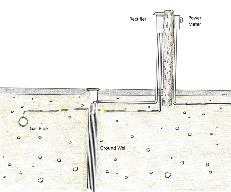
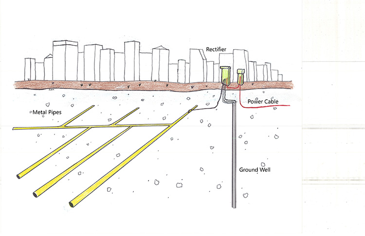
So, an ICCP system is just a little more involved than a GACP system. The DC current moves outward from the rectifier and downward on extensive rods drilled into the ground – the current moves out from the end of the ground rod – out to the ends of the steel pipes – and then on the pipes back toward the rectifier – then connects to the rectifier through an insulated wire.
In this way a completed circuit is produced – and yet – the only point where current is exiting a conductor is at the end of the ground rod – and therefore – it is the only corrosion point.
Those ground rods are drilled very deep into the ground, usually a minimum of 500 feet (152 meters), and in groups of maybe 6 to 10 rods. Only one rod is connected to the rectifier at a time. After many years, and the corrosion of that first rod, then the wire is disconnected and another rod will be connected at the rectifier. This group of deep rod anodes is a ground well. This arrangement is technically an anode, but more specifically it is a group of lengthy anode rods, with only one being used at a time.
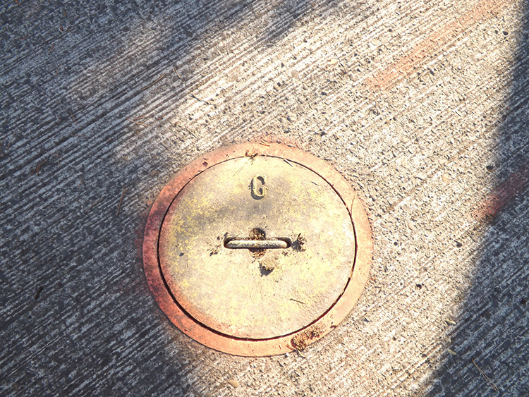
Above ground, an ICCP system doesn’t look like much. There is a rectifier box, a power box, and a small lid nearby that covers the ground well. And yet, the cost of drilling and placing these ground rods makes this a very expensive little plot of land.
Overall, ICCP is a much stronger CP system. It is the standard system used on petroleum pipelines. It is also used on some gas distribution systems in areas of low soil conductivity, such as sandy coastlines.
All CP systems need to be checked on a regular schedule. You can not just bury a series of pipes and then expect that everything will function properly. You need to ensure that the current on the pipes is moving toward the anode or ground well, and that it is enough current to be effective. This is the purpose of Test Stations.
Test stations are very common on petroleum pipelines with ICCP, but can also be found on high pressure gas mains which are using anode beds.
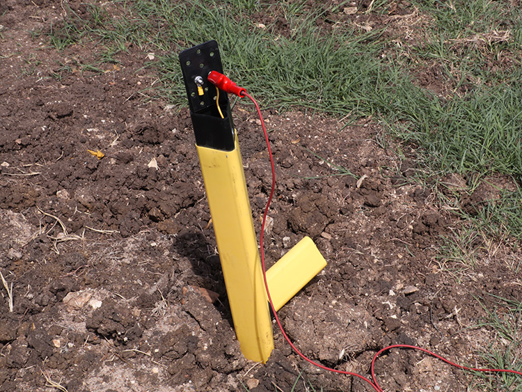
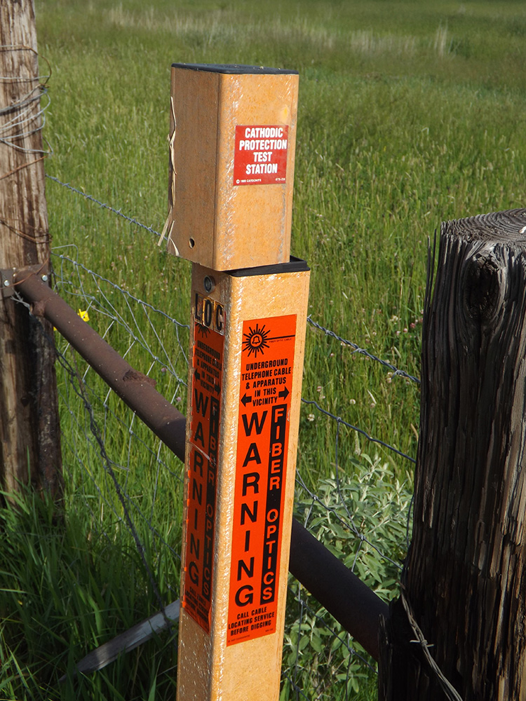
Test stations are usually very simple posts of varying material. They may be steel, or plastic or they may be made of carsonite. They may even be flush mounted and hard to spot in the field.
Basically, a test station is nothing but a connection post with several wires coming up from the ground. These are not tracer wires. Any pipe with a test station is obviously a steel pipe and does not have tracer wires.
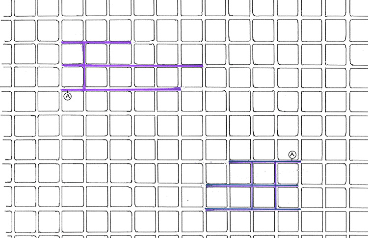
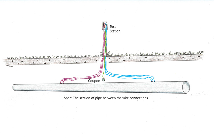
These test station wires are spot welded (chemical weld) on to the pipe below. There will usually be several wires, all the same color, which go downward – then extend out to a farther position on the pipe. Another set of wires – in a different color – will go downward – then extend out to a farther position in the opposite direction.
So, the pipe usually has two sets of wires, each chemically welded in opposite directions on the pipe, and this space between them is a span. It is the span which is being tested. The CP tech connects a multi-tester to the wires and can determine if the current is moving toward the anode, and exactly how strong the current is at that point.
The purpose of having multiple wires is simple redundancy. If one of the wires is accidentally yanked out of the ground, or corrodes, one of the other wires can be used, and there would be no need to dig up the pipeline.
The color of the test station wires denotes which direction from the test station the wire is attached. This is of course crucial for the CP techs. They can not determine if the current is moving northward towards the anode unless they know which wires are attached toward the north. However, unlike telephone cables, there is no national color code for these wires. Each pipeline owner may be using a completely different color compass.
There may also be an additional wire or wires that attach to a buried coupon. We normally hear the word “coupon” in conjunction with grocery stores. However, in its basic meaning a coupon is a representative or sample of a major item. In the pipeline industry, a coupon is a small piece of the pipe that was not needed, and is buried a short distance from the pipe with an insulated wire running up to the test station. This allows a comparison check between the pipe and the coupon.
If you are a utility locator, you will notice that no matter which wire you connect to – the signal will always go in one direction – the direction of the anode. This is because all of the wires are directly connected to the pipe. If you connect to the coupon wire then there will be no signal at all.
You should never try to locate against this current pull. It is going to be strong and consistent. You will only end up pushing your signal on to a different utility. If the pipe is running east/west and the signal is pulling to the west, then the solution is simple. Look for the next test station to the east, connect there, and that connection will give you a good signal right back to the test station you started out at.
Since all CP is a manipulation of current on pipes, it is reasonable to question whether that CP current could be detected by an electronic instrument, such as a Pipe & Cable Locator, and therefore be traced out. The answer is yes, but only on one of those CP systems. This is the purpose of the CPS Passive feature on many P&C Locators.
The current on GACP is originating from many different sources. It is stray current coming from electric power, garage door openers, wi-fi, radio stations, TV stations, cellular phone transmissions, and many, many more.
These are all operating on different frequencies, and a very wide band of frequencies, so it is practically impossible to set an instrument to detect them all at the same time. Individually they are all too weak, and combined they are too diverse.
But ICCP does offer a different situation because that current is specific. The rectifiers on ICCP systems alter the AC current of electric power, to a DC current in order to push the current in a single direction.
In the United States, as well as Canada and South America, all electric power is generated at 60 Hz. The rest of the world generates electric power at 50 Hz. So, a rectifier in the U.S. will convert 60 Hz current to DC current, but converted DC current does not have frequency. However, the reason converted DC current does not typically have frequency is that the alteration of AC to DC also typically includes electronic filters.
That small box-type structure on the power cord of your laptop is a rectifier – and a filter. It converts the AC coming into your house, into the necessary DC to run through your laptop. And it filters out the ripple current.
When you see alternating current on an oscilloscope, it appears as a sideways S shape. The left side portion is the positive amplitude (forward motion), and the right side portion is the negative amplitude (backward motion). Together they represent one full cycle of AC.
When AC is converted to DC in the rectifier it is taking a single cycle of AC and converting it to two cycles of DC (both of them positive amplitude). This produces a direct current, only moving in one direction, and yet, it is not “smooth” DC current like that coming from batteries. Because of that ripple effect, it has phase, and frequency, and wavelength.
In other words, the alteration of AC to DC without a filter does not produce the type of current we would normally expect from DC. It produces DC ripple current.
To simplify all of this, the current being pushed onto the pipes in an ICCP system almost always consists of DC ripple current, and that ripple current is operating at double the frequency of the power going in to the rectifier. So, in the U.S. and many other countries, there is a 120 Hz ripple current on the pipes. Construct a P&C Locator, include a frequency option of 120 Hz, and it can now detect that ripple current.
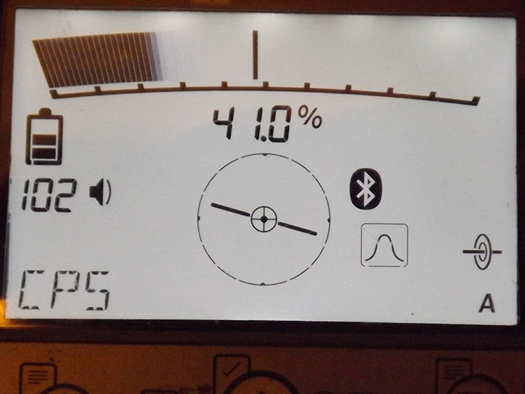
On some instruments that ripple current may be labeled as “120 Hz”, and may also include an option for detecting that ripple current in Europe, Australia, Asia and Africa, and therefore be labeled as “100 Hz”. Or they may just set the receiver to cover the full bandwidth of 100 Hz to 120 Hz, and call it “CPS”.
All of these are detecting the ripple current on ICCP systems. It is all CP Passive. The signal will be stronger as you get closer to the rectifier, and weaker as you get farther away. And very importantly this only occurs on the ICCP systems, not those which use simple sacrificial anodes.
Also, importantly, this is not the best method of tracing out pipelines. It does however serve as a great way to double-check the utility line, or to trace it out if there is no other method available. Direct connection at a test station or any other access point should always be used if at all possible. Follow out the pipeline using direct connection – then switch to CPS and follow the line back. You have now traced out the pipe using two completely unrelated methods: one, using current applied to the pipe by your transmitter; and two, tracing out the DC ripple current which is being applied to the pipeline through the rectifier. That is the most secure method of locating any pipeline.
In the past, anyone in the U.S. working with corrosion or pipeline integrity had to be “NACE certified”. This could be anything from a technician checking on test stations, all the way to designing CP systems.
However, this year, 2021, NACE has joined with the Society for Protective Coatings and now formed the Association for Materials Protection and Performance (AMPP). This is an international organization offering 23 different certifications. This includes corrosion protection on ships, bridges, and various other areas as well as of course preventing pipe corrosion. The AMPP has offices in North America, Africa, Europe, South America and Asia. They can be reached at www.ampp.org
One last point, CP of either kind is very uncommon on water pipes, but it is used on some water systems, especially on very large water pipes. It is even more rare on other types of utilities, but can be seen. A sheathed fiber optic cable near a group of petroleum processing plants with a multitude of steel pipes is going to collect some of that stray current. Placing CP on the fiber cable will prevent the sheathing from corroding away rapidly.