TELEPHONE – POTS
Telephone was invented by Alexander Graham Bell in 1876. There were several different companies that originally sprung up to take advantage of the invention, and telephone cables and systems operated in a number of different ways. In 1888 telephone became very standardized as twisted pair copper cable, and the addition of load coils and repeaters completed the system.
This original system remained as the only type of telephone until the advent of the T1 system in 1963. Then DSL and FTTx came along in the 1980’s and now there were a number of different types of telephone technology and architecture. Now the original system required a specific name to identify it from the later versions. The name for that original system became Plain Old Telephone System, or POTS. Any telephone cable that is not T1, DSL, or part of an FTTx system, is a POTS line.
Though POTS lines are disappearing rather rapidly, it helps to understand that original system because there are still a number of those lines out there. Another point is that DSL is actually built on a POTS framework. They utilize the same cables, and only replace some of the features.
Although there is a lot to cover with telephone, most of the U.S. had only one phone company for over a century, so understanding that one company can be very useful no matter which part of the country you are working in.
One helpful point is that in the original telephone system, POTS, there are no energized cabinets, pedestals or features of any kind. The electric current to operate a POTS system is the minor current on the tip and ring wires and comes strictly from the Central Office. Any telephone cabinet that is energized is obviously a part of a T1 system, DSL, or FTTx.
TELEPHONE – POTS
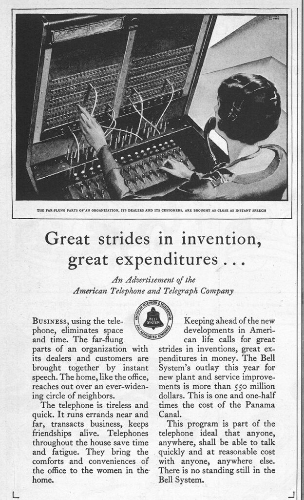
Up until the 1980’s most people simply called it “the phone company”, but the official name was The Bell System, and it actually was made up of four companies: Bell Laboratories conducted the research and inventions in communications; Western Electric built the cables, pedestals, repeaters, the telephones themselves, and almost everything else in the system; AT&T (American Telephone & Telegraph) was a private company that was absorbed by the Bell System and became the long distance carrier; and Bell Telephone Company which was the local systems.
The Bell System was always operating as 22 different regional operations, technically the 22 BOC’s for Bell Operating Companies, though all of them still one company. By the early 1980’s the Bell System disappeared and was replaced by what the media called “The Baby Bells” but were officially known as the Regional Bell Operating Companies (RBOC). The original 7 RBOCs, “Baby Bells”, were formed from the 22 BOCs.
TELEPHONE PLANT
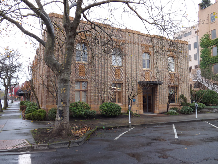
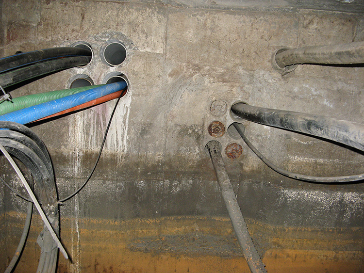
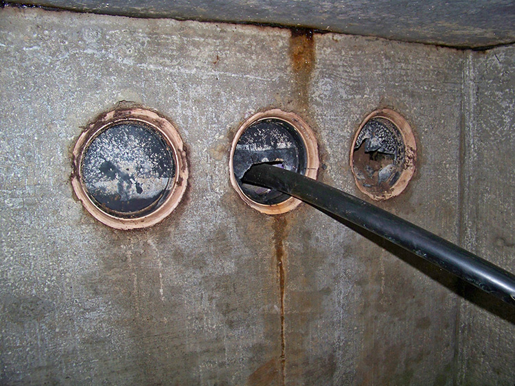
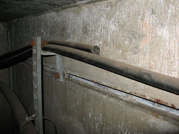
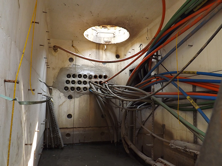
Telephone systems are centered at a Central Office or CO. The largest city in the State would contain one or two full size COs, and possibly more. These structures would probably be a multi-story office building in a downtown area where maintenance, planning, administration, and even billing services are handled. Connected to the building, and below ground, would be a very large cavern of phone and fiber cables. These underground areas can be multi-level, and often have their own lighting and air conditioning systems.
A duct run or duct bank, is a group of telephone cables, and possibly fiber, that are buried together in a common trench. A duct run is buried from one phone manhole to another, and originates at a CO. When you hear the term “duct run” most people visualize a solid structure with the cables pushed through the structure. While certainly the standard, that is not always correct. There are a variety of duct runs in existence. They can be a solid molded concrete structure, a simple concrete “cap” on top of the conduits, a poured syncretic material over the conduits, or sometimes simply a group of conduits running together. Often there are several empty conduits in a duct run to accommodate future needs, but depending on the usage demands that may not always be true. The average duct run consists of 9 conduits, but more than one duct run may travel between manholes. The number of total cables in any duct structure or group of ducts can vary significantly and the total capacity can be quite large. There may be as few as a single phone cable and 8 empty conduits, or there can be 18 or more conduits, with almost all of them containing either a phone cable or fiber cable.
Fiber cables can be found in most phone manholes today, however, there are still numerous older duct runs that do not have any fiber cables.
CROSS CONNECT
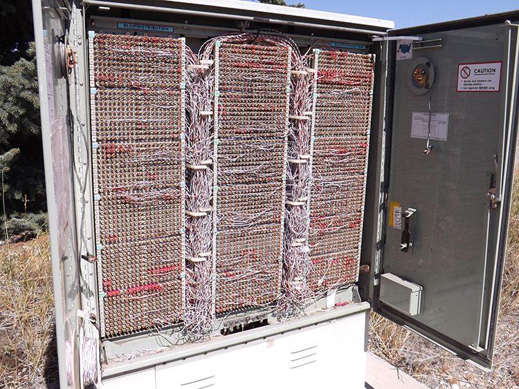
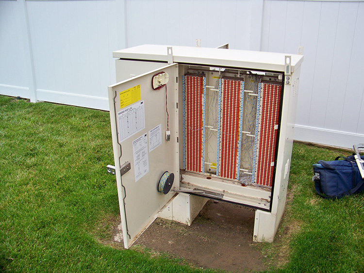
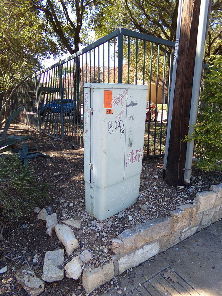
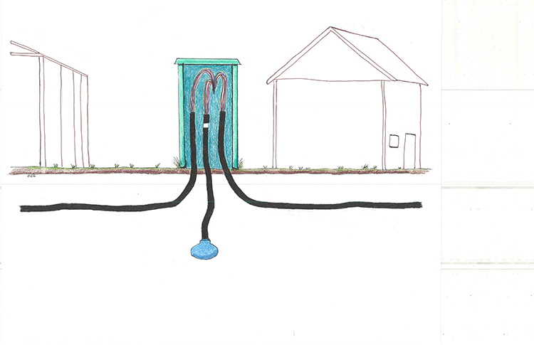
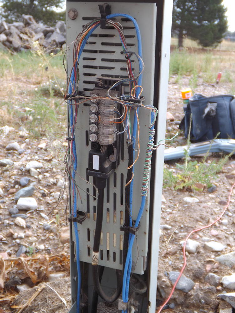
Despite the large number of different types of phone cabinets cross connects, also referred to as Cross Boxes or X-Boxes, are usually easy to identify. While produced in a wide variety of styles, they are usually distinguishable by their doors. Almost all cross connects have two doors on the front of the cabinet that swing out. Once you open these doors, the reason behind the name of the structure becomes very apparent. The entire front of the cabinet consists of either a massive terminal block for wire splices or, in older structures, a series of small terminal blocks. Instead of flopped wires with small splices as viewed inside in AP or a pedestal, the tip and ring wires in a cross connect all splice into the front of the terminal block. Every tip and ring wire splice is very visible and very accessible at the front of the terminal. This configuration allows for the easy connect or disconnect of individual telephone service by telco technicians.
A cross connect is the point where the phone cables cross over from transmission (feeder) to distribution. Every call made or received from a specific phone number uses the same tip and ring wire each and every time all the way to the cross connect. Once at the cross connect, the system changes. Leaving the cross connect to the CO, the call will be carried on whichever service wire may be available. Telephone service lines are only dedicated from the cross connect to the building.
PECULIAR CROSS CONNECT
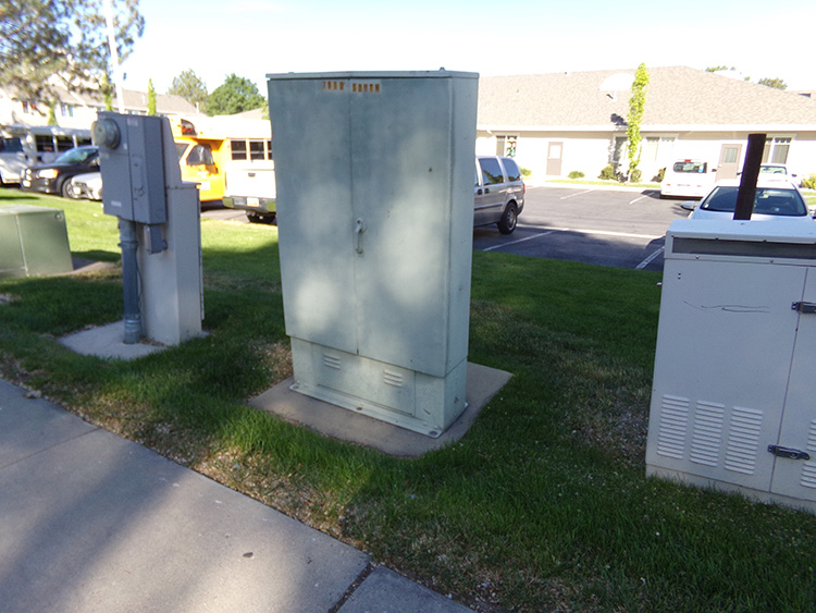
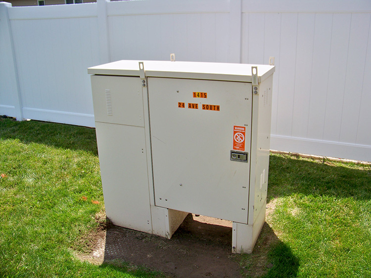
One particular cross connect cabinet was installed in large numbers in the 1990’s, although it seems to have fallen off in popularity since that time. This cabinet consisted of a set of doors, one on each side, and a boxed cover that had to be slid off the side. The problem was that the cover could only slide when both doors were locked in the open position. This rather unusual feature was a bit puzzling for a technician exposed to the cabinet for the first time. The doors open just like any other cabinet and are actually quite easy to open, but the doors do not provide access to the cables, only the terminal blocks. In order to reach the cables, the top must be removed also. These cabinets are easy to recognize because they are much wider than they are tall.
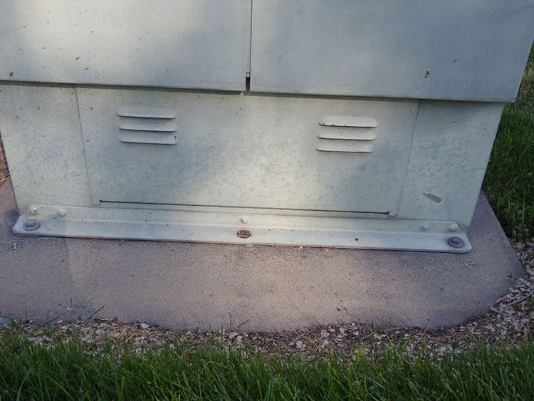
In order to access the cables, the first thing a technician must do is open the doors and pull them out into the open-locked position. The cover on the bonding straps will not slide off unless the doors are in the open-locked position. The cover must be shifted slightly upwards. A flathead screwdriver is the best tool to use for accomplishing this. After the cover is shifted it should be fairly easy to slide the cover off by pulling it away from the doors of the cabinet. This will expose the area where the bonding straps attach to the cabinet.
ACCESS PEDESTAL
An Access Pedestal or AP is a large pedestal sometimes called a 1248 that allows easy access for telephone technicians. The term 1248 is a reference to the size of the cabinet. These structures are usually 12 inches deep, and 48 inches high, although some of that height is below ground. The major difference between a Pedestal and an AP is that the AP is a larger structure meant for housing cable splices, but not usually for phone service connections.
An AP has two major designs. The older version features wide opening doors, often in both the front and back, while the more recent AP disassembles into 3 pieces: front, back and top. With the ability to remove all of the structure housing, the technician has full access to all the cable splices inside. Occasionally APs will have a phone service attachment also, but this is not common.
PEDESTAL
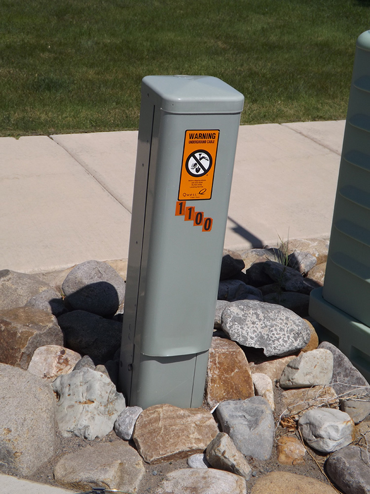
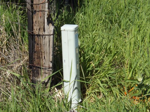
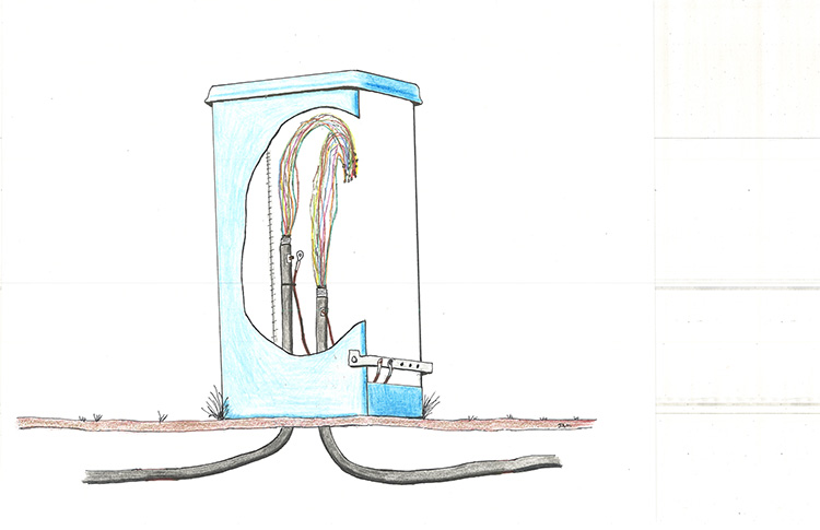
The most common structure in any phone system is the pedestal. These enclosures hold the connection between the cables and between cables and services. The most common size for a pedestal is about three to four feet high by six inches wide.
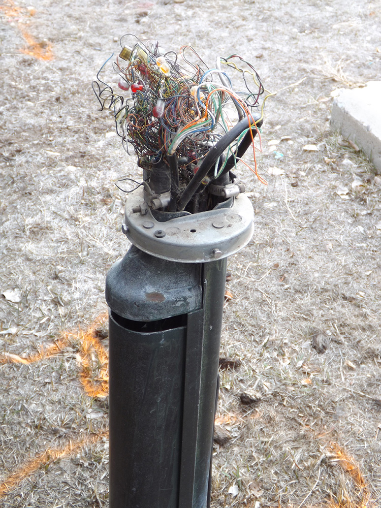
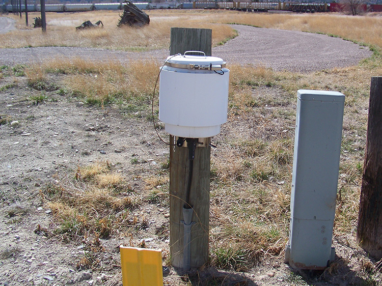
The first widely-used pedestal was a metal post with a bullet shaped structure on the top, sometimes called bullet pedestal or beehive pedestal. The cables and services came up from the duct run inside the post, and were then accessible to the technician once the bullet top was removed. These pedestals were poorly designed and were replaced in time with the box-type structure we still see today. On rare occasions an old bullet pedestal can be found in the backyard of a home in a very old neighborhood.
All of these earlier pedestals were made of metal, but modern pedestals (those produced in the last 30 years or so) are usually plastic. They all have similar construction, a plastic covering that lifts straight up, revealing the entire interior of the pedestal.
Telephone cables are bonded to each pedestal with bonding straps. These are short, usually insulated, wires that are connected to the cable sheaths.at one end, and to the pedestal at the other end. With plastic pedestals the bonding strap is bonded to a metal post inside the pedestal.
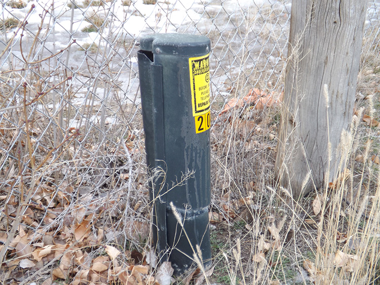
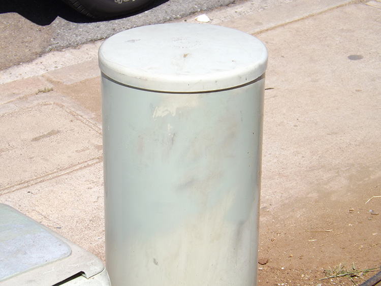
One of the many tried-and-failed structures in the utility industry is the encapsulated pedestal. Common in the 1980’s, they quickly disappeared in most parts of the country. Encapsulated means capped, or sealed, therefore an encapsulated pedestal, or encap, were round flush-mounted phone pedestals made of plastic
REPEATERS & LOAD COILS
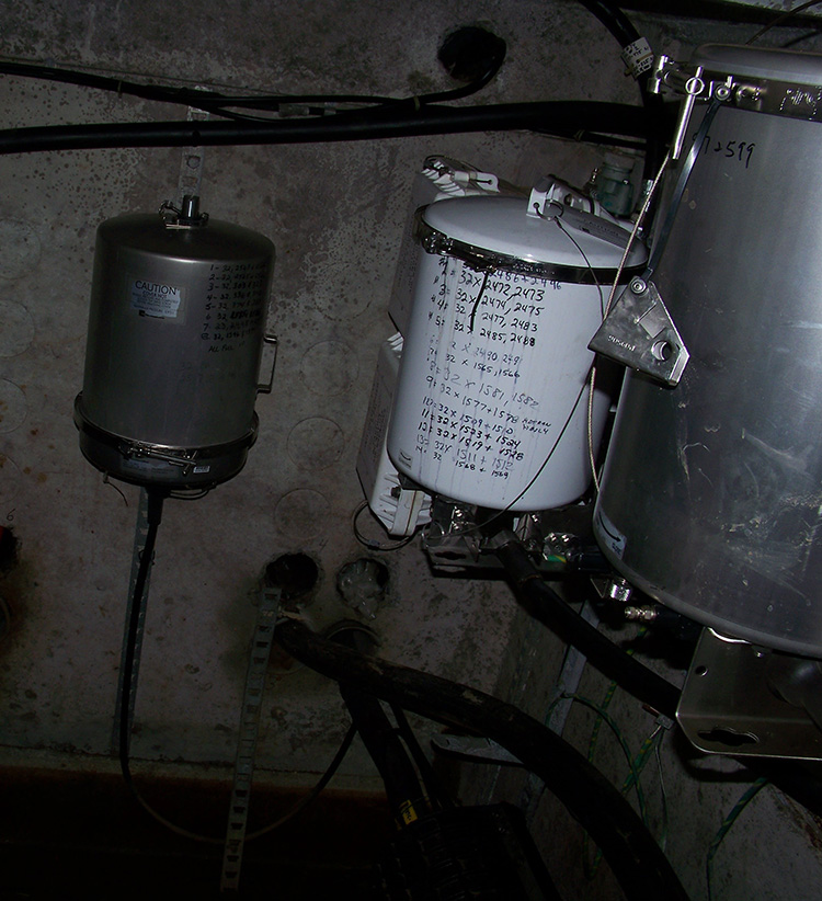
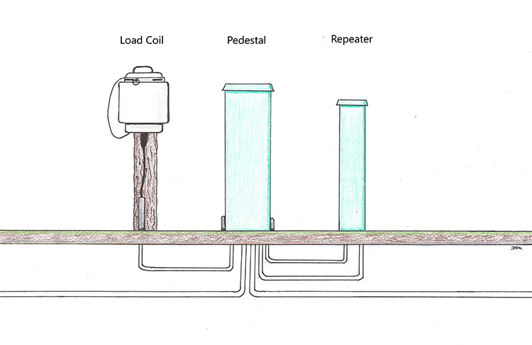
Anywhere POTS phone cables can be found, so can Repeaters and Load Coils. Load Coils and Repeaters make long distance calling possible. Both are very simple structures invented to improve signal quality on the telephone line. They can look somewhat similar, but they operate very differently.
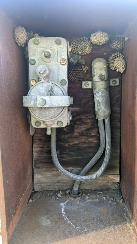
Telephone cables carry a small current on them, but that current must be balanced for the voice signal to be heard. If it isn’t, the voice over a long distance connection sounds like listening to someone underwater. Load coils, the solution to this problem, were invented by Michael Pupin of Columbia University in 1899. A load coil is basically a stack of metal rings, with thick insulation, and a stubbed line running to the cable. The load coil works with the current on the cables, not the voice signal, so only a single phone cable connects the load coil to a 3-way splice located in a nearby phone structure. A load coil is usually abbreviated on phone prints as LC .
Another needed invention was patented by Lee de Forest in 1906. Technically, it is best described as a triode vacuum tube, but it was soon being referred to as a Vacuum tube repeater, or more simply as a repeater. Where load coils balance the current on the line through a single cable, repeaters are an in-and-out device that continually clarify the voice signal.
The actual voice signal flows through the repeater, so repeaters always have two cables, one in, one out. Repeaters are often abbreviated on phone prints as RPTR.
Together these two inventions made it possible to send a phone signal over an almost unlimited distance. Up through the 1950’s repeaters were large enclosures, about the size and shape of a large suitcase.
BURIED LOAD COILS
Although load coils are usually above ground structures they are also buried in some areas. Telcos that bury load coils have a set procedure for indicating their presence. Set markers will be placed on the cable that goes to the load coil, usually a band of white colored tape.
TOLL & TRUNK CABLES
In the early days of telephone, a call placed to another State was considered a long-distance call. Calling across town wasn’t considered long distance but if the call had to be routed through a different CO it was considered a “toll call” and an additional charge (lower than long distance charges) was assessed. Toll cables run from CO to CO with few connections along the way. These cables are usually small 25 pair cables, and can be within a duct run or by themselves. Depending on their age, they can be old lead or the newer PIC cables.
Telephone trunk cables are usually large 600 pair (or bigger) cables, and are used to connect distant neighborhoods with the closest cross connect. Trunk cables are not always labeled as such on phone prints. They usually exit a cross connect, bypass nearby AP’s and pedestals, and run to a neighborhood much farther away.
Due to their layout within the telephone system, trunk cables and toll cables have a very high damage rate, much higher than their percent of plant would reasonably indicate. The purpose of these cables is to bypass the local distribution system and because they rarely connect into pedestals or AP’s, locate technicians often forget that they may be in the vicinity.
SERVICE WIRES
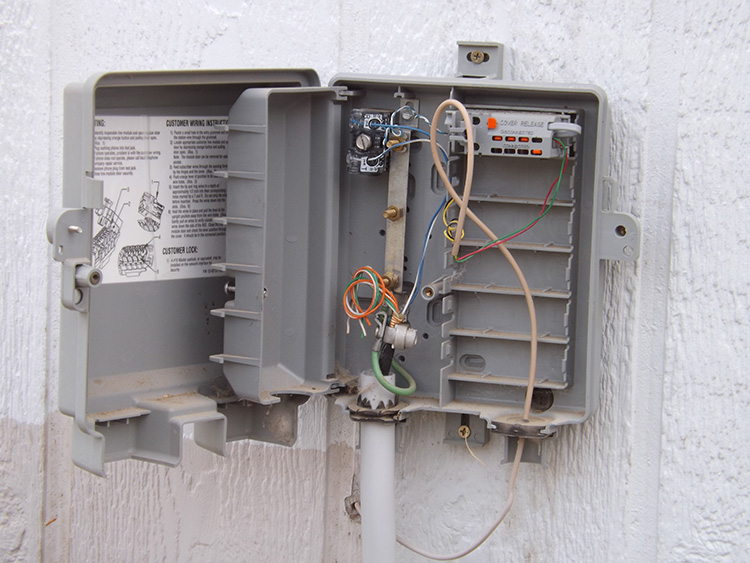
Phone service lines connect to a house at the Single Network Interface or SNI, which is also commonly known as a Protector. The older SNI’s were small terminals, only a few inches across, and covered with a rubber guard that was fastened by a standard screw. Modern SNI’s are about a foot across, and look like a semi-flat plastic box. Usually secured with a hex lock, a SNI wrench is required to open the outer cover. There may also be an inner cover that requires a flat-head screwdriver to open it.
RURAL SERVICE WIRE
A farm house in the 1920’s with a single telephone service was not a big money maker. It could take years to recoup the cost of placing service wire to the farm house in the first place and any break in the service would mean a costly repair that could add several more years to the break even date.
The 1934 Communications Act mandated phone service for every home in America. It not only required phone companies to supply service to farm houses if it was requested, it also offered financial rewards to them to do it.
The invention of rural service wire was a very simple invention, a single pair phone service with a rigid outer jacket, and copper-clad steel conductors instead of full copper conductors. As these wires were single pair side by side rather than twisted wires it was much cheaper to produce and it could hold up to severe weather conditions better than the standard service wires. Called Rural Service Wires or RSW, they are also commonly called BSW for Buried Service Wire or ASW for Aerial Service Wire. Another common acronym is CRW whose meaning is a little obscure but probably stood for Communication Rural Wire. Whichever name is used, they all imply a single pair phone service of usually rigid material that will run for a long distance in a rural area. Because of their length, Rural Service Wires are the only telephone service that will usually be indicated on phone prints.
Rural Service Wires are also quite often used for tracer wire for fiber optic cable, and used as interconnects in traffic system.
TELEPHONE TERMINOLOGY
AP (ACCESS PEDESTAL)
Many of the larger telephone pedestals are for cable splices only. They usually do not have any phone services inside, just cables. They are also usually constructed in a 3 piece format, a top and 2 sides. This allows good access to the cables since the entire above ground structure can be easily removed, and is responsible for a common term of access pedestal or AP in many areas. They are also commonly known as a splice box or splice cabinet.
CO (CENTRAL OFFICE)
The term “central office” was coined by Alexander Graham Bell himself. It was meant as a rather vague description of a building where all of the phone lines in a particular region came to a central connection.
In a large metropolitan area a CO is usually an office building with numerous employee offices, and a connecting vault. The vault may very well be more of an underground complex. They can be multi-storied structures with literally hundreds of copper and fiber cables. Above ground the CO area may seem to be just the office building, but underneath the parking lot, the landscape, and the even the street, there can be a massive vault two or more stories high, with it’s own lighting system and air conditioning.
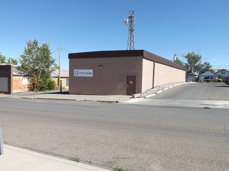
In a rural area a CO may be a building no larger than a shed, and with as few as three or four cables total. Other CO’s will fall somewhere in the middle. They may be about the size of a convenience store with two or three employees working inside, and a couple of standard size manholes out front. Typically all CO’s, whether large or small, are brick buildings.
COPPER
Telco technicians often use the word “copper” when referring to any telephone cable (lead, paper, or PIC cables) because they all have copper conductors in the tip and ring wires. So, it is common to hear phone techs refer to cables as either fiber or copper.
CROSS-CONNECT aka CROSS-BOX aka X-BOX aka SAI
A large phone enclosure that contains a series of terminal boards. The enclosure has actual doors that open instead of a lift-up cover like a phone pedestal. This is the cross over point between manholes and the above ground phone enclosures (AP’s and pedestals). All phone cables from the CO to the cross-box are considered feeder cables. From the Cross-box to the building, they are distribution cables. Cross connects are technically known as SAIs, for Service Area Interface.
DIRECT BURIED CABLE
Any cable that is not in a conduit or duct run is a direct buried cable.
DUCT RUNS
Duct runs make up the main transmission portion of a phone cable plant. The Telcos refer to these main runs as feeder lines, not transmission lines.
ENCAPS
Encaps can denote a number of different things. The one thing they have in common is an encapsulated splice. This is any phone splice where the connections of tip and ring wires are completely sealed. Many phone pedestals have encapsulated splices, but there are also small round flush-mounted phone pedestals that are commonly called encapsulated pedestals. In this case, the entire cable is left below ground, and the encapsulated splice includes the connections to the service wires, and only the service wires come up into the round pedestal. Encapsulated pedestals were only placed in some small areas, mainly in the 1980’s.
LOAD COIL
A small metal coil which is attached to a single telephone cable, then connects into a 3-way splice in a cable run. Load coils provide an even current in the telephone cable run. They are extremely necessary and common throughout a POTS telephone cable plant. They can be seen attached to short poles next to telephone pedestals, inside telephone cabinets, pole lines, and even inside manholes. They are often labeled with the abbreviation LC on the load coil housing, and often on phone prints.
In most parts of the country load coils are above ground in a separate enclosure. In a few regions load coils are buried directly under the phone pedestals. In this situation, the cable extending downward to the load coil will have a white striped mark on it.
PEDESTAL
Any above ground enclosure that connects distribution cables to other cables or to service wires. Telephone pedestals originated in the late 1940’s with direct buried cables as a splice point from phone cable to service wires. Telephone pedestals were originally all metal, and built in a domed shape at the top, often called bullit peds, or beehive peds. Most of the modern peds are plastic. Phone pedestals are typically green or light brown in color.
PIGTAIL CABLE
Some phone cables have been manufactured specifically for suburban neighborhoods. The cables come from the factory already containing regularly spaced splices, each one a 3-way splice where one cable can be pulled up into the phone pedestal. These were created to take advantage of the modern planned neighborhood where each property has the same width. Pedestals are normally placed at a point two property lines away from each other so that each ped can feed services to two houses if placed in the front of the lot.
REPEATER
A device for clarifying the signal on telephone cables, they operate off of the mild amount of current already present on the phone cables. Originally, they contained vacuum tube electronics, but the advent of solid state electronics in the early 1960’s allowed them to be built in much smaller sizes. There will always be a large number of them throughout any POTS telephone plant.
RURAL SERVICE WIRE
A very rigid single pair telephone service wire made of copper-clad steel, that runs for a long distance, buried or aerial, and usually included on telephone prints. Also known as RSW, CRW, BSW, and ASW.
SNI (Single Network Interface) aka PROTECTOR
The small plastic connection box attached to the side of residential buildings. This is where the telephone service wires enter the house. Originally these were small rubber housings, and only about 2 inches wide. The modern versions are about 8” X 10”, and made of plastic. These are a common connection point for locating service wires.
The phone connection boxes on commercial buildings are sometimes called just Network Interface, because they connect an entire cable into the building instead of a single phone service.
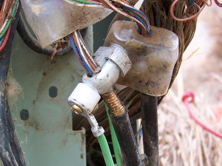
SPARK GAP INSULATOR
A very small device found in modern telephone pedestals. They will be attached to a telephone service in-between the service and the grounding connection for the service. These are used to prevent electric shock on a telephone during a power surge.
TELCO
Telephone Company, specifically a true phone company which can provide telephone service to individual residences.