
Coaxial cable was invented in the 1930’s to provide high-capacity telephone communications, running thousands of telephone calls on a single small cable at different frequencies. The very first coaxial cable was put to use when an experimental coaxial cable was installed between Toledo, Ohio and South Bend, Indiana in 1937. Then in 1941 the first commercial coaxial cable was put on-line between Minneapolis, Minnesota and Steven’s Point, Wisconsin.
Coaxial cable was then used heavily by the military during World War II as an easy communication line to install, and provide multiple lines. After the war there was now a pile of surplus coaxial cable and electronics, and a large number of military veterans with a lot of experience in that area. This coincided with the beginning of regular television broadcasts starting in 1946.
Broadcast television was of course very expensive, and the networks focused solely on the metropolitan areas. Television sets were available, and anyone could purchase a TV, but it served no purpose to own a receiving device when the sending device was 100 miles away, and maybe much more.
In 1948 the same event occurred in three different states, Oregon, Pennsylvania, and Washington. Several owners of TV shops in small cities had all had the same basic idea: broadcast TV was available, but too far away for most people in town to receive it, and there was plenty of war surplus coaxial cable and communication equipment available at very cheap prices. It is usually thought that Ed Parsons of Astoria Oregon was the first to make it happen. It is hard to sell TV sets when the public is aware that there is nothing to watch, so Parsons installed an extremely large antenna at his electronics shop to receive the distant signals, ran cable to several nearby homes, and the homeowners then had a strong desire to purchase a TV. Parsons then began stringing more cable from one housetop to another, with the homeowners consent of course.
Shortly thereafter John and Margaret Walson of Mahoney City, Pennsylvania did the same thing. They made an agreement with the local power company to allow them to install coaxial cable on the power poles. A very large antenna on the roof of their appliance store to receive broadcasts from the larger cities of Pennsylvania, and coaxial cable to transport the signal to the nearby homes, and then John and Margaret’s appliance store was suddenly selling a lot of TV sets. The original name for this system was Community Antenna Television, or CATV. The name would change a few more times, and yet the acronym CATV would always remain.

These towns were willing to allow coaxial cable to be placed in the public right of way, but they usually wanted some access to what was being offered. The town would usually want some programming that promoted the town in some way. There were also educational programs, and there was a desire for the public to create their own programs. CATV providers allowed the general public to create their own little TV shows, the “studio” sometimes being someone’s living room. They could be fishing shows, handicrafts, art programs, and some programs that were hard to define. By the 1960’s cable TV was heavily involved in these community programs, and it became commonly referred to as Community Access Television. Community Access TV always included a lot of rather weird programs, and would serve as the inspiration for the movie Wayne’s World. Larger companies began getting involved in CATV, and the programming would become more professional over the years. Today, Community Access programming is rather rare.
Community Antenna Television had altered to Community Access Television and eventually became known as simply Cable Television, but the moniker had remained the same – CATV.
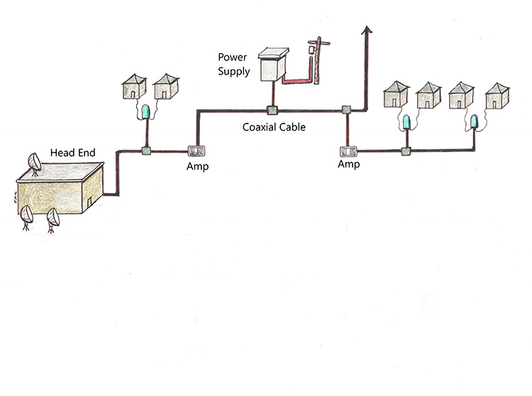
The centralized point of any cable TV system is called a Head End. A newer name for a cable TV head end is MTC for Master Telecommunications Center. Some CATV operators may only have one head end within the city, but it is becoming far more common to install additional remote head ends in other parts of the city which are connected in a very wide pattern around the main head end. The main head end is where the satellite signals will be received from various sources, and electronically processed for application to the cables. Each communication satellite carries 24 transponders, so the number of satellite dishes does not represent the total number of channels the cable TV system is carrying. Head ends tend to be quite noticeable because of the satellite dishes, although TV affiliates also have a large number of satellite dishes on and around the building as well.

In CATV systems the conductors in the coaxial cable are referred to as the “Go” and “Return” conductor. The Go conductor is the inner conductor, usually made of steel and an outer cladding of copper. The Go conductor is the true carrier of the communication signals. The Go conductor is then surrounded with a dielectric foam, and then the Return conductor makes up the outer layer. The Return conductor is usually made of aluminum, and protects the inner conductor from outside electromagnetic interference.
Some aerial coaxial cables have only this type of structure, but many aerial cables and all buried coaxial cables also have an outer polyethylene jacket to protect the cable from moisture, UV rays, and other damage. So, aerial coax may have a black poly jacket, or it may be all aluminum.

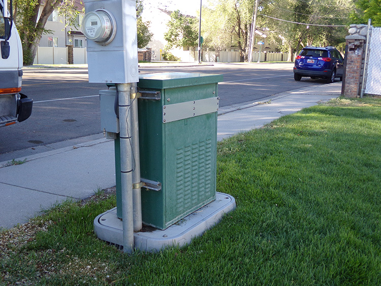
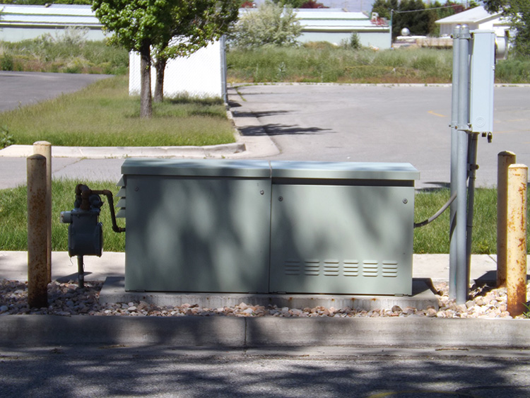
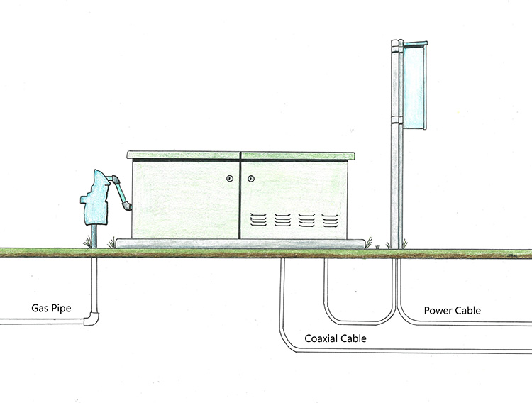
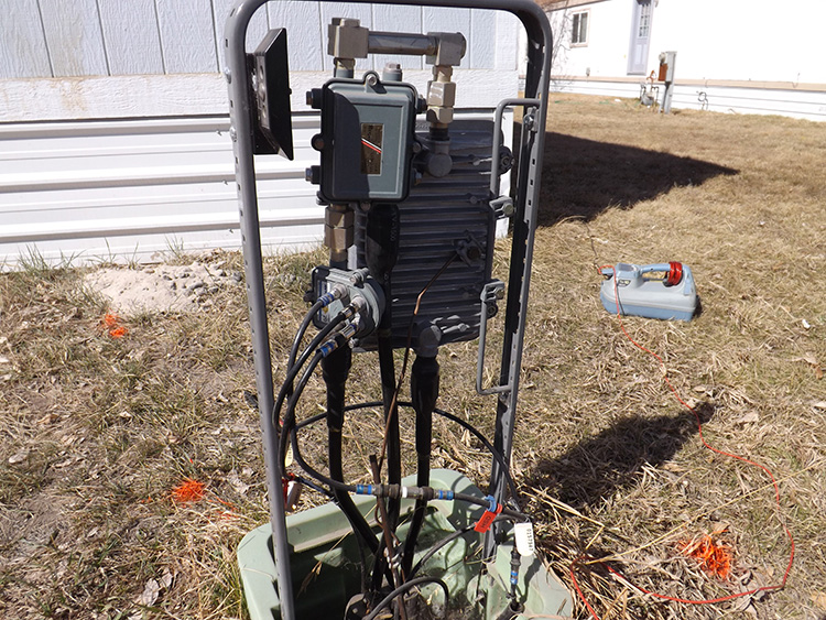
Electric power must be injected into the system as the cable gets farther from the Head End, and that is the purpose of Power Supplys. Every power supply has battery packs as well as the electric power coming in on a standard secondary power cable.
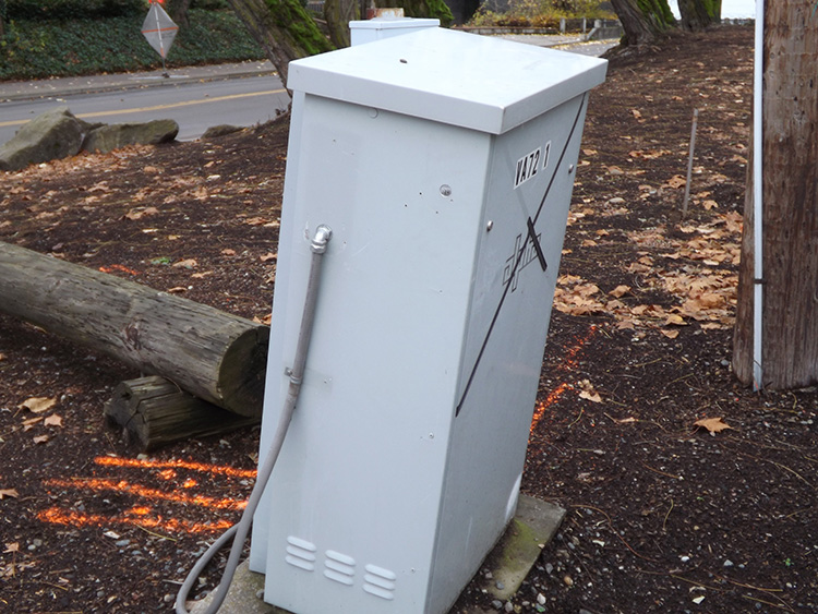
Many Power Supplys also have natural gas service which can kick on automatically during a power outage, and operate a small generator in the cabinet. These Power Supplys are built lower to the ground, with the generator contained in one side, or as a separate unit next to the Power Supply.

The amount of current on coaxial cable is usually 60 to 90 volts as it exits the power supply, and is then depleted along the route, all the way to the taps where the services are connected. This is not a very high voltage, but much higher than a car battery. The amount of current used in the 1950’s and 60’s was much higher, and could easily be lethal, but the CATV technology is continually allowing for lower and lower voltages to be used.
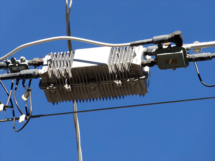
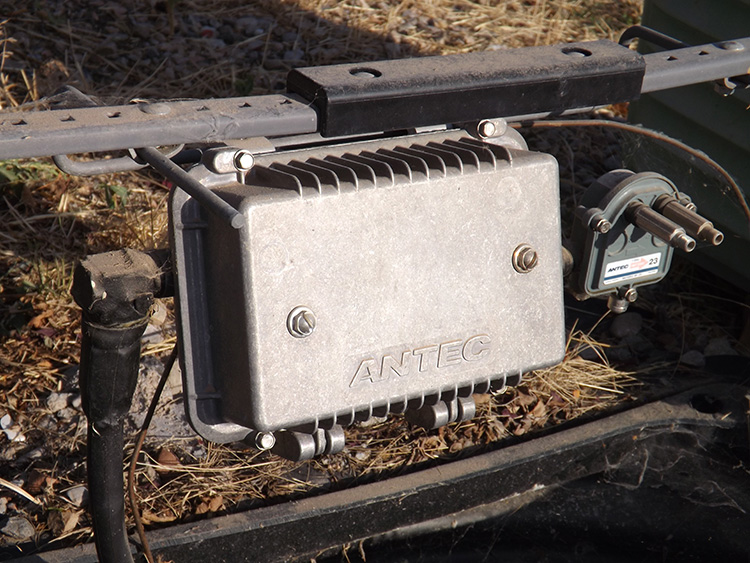
Amplifiers are the next feature downstream from a power supply. They are made of aluminum and have a rippled exterior to dissipate heat. Amplifiers may be aerial or ground mounted. They are very small, only about a foot long, and when ground mounted they are typically within a cabinet that may have splitters as well as the amplifier. Amplifiers are very common in any CATV plant, and there can be 20 or 30 amplifiers downstream from a single power supply.
The coaxial cables are referred to as trunk, feeder, and drop. Those terms are not unheard of for other utilities, but with CATV they are the standard. A coaxial cable is seen as a trunk cable when it is upstream from the bridger amplifier, and a feeder cable when it is downstream from the bridger amplifier. However, this is not a visually recognizable feature. Bridger amplifiers look like any other amplifier, though they will be identified on the CATV prints.

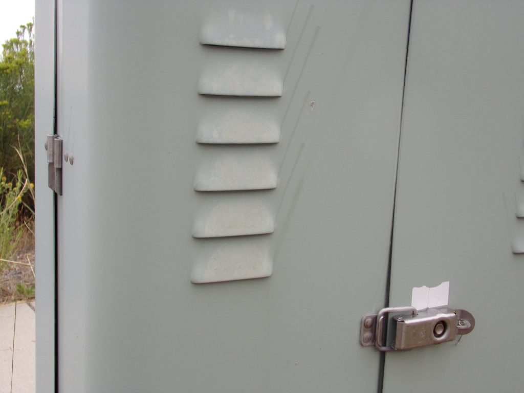


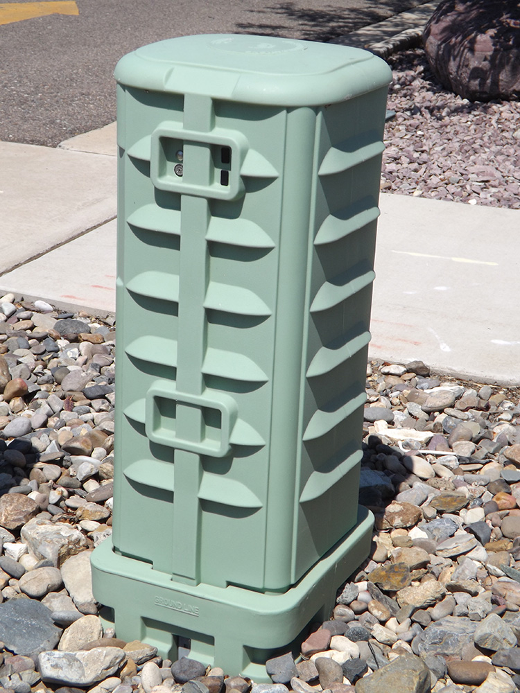
The most common cable TV enclosure is pedestals. Originally, the pedestals were metal. Since the earlier amplifiers operated at high voltages, the metal pedestals had open vented slats to dissipate any heat build up. As the voltages were lowered over the years, the need for vented slats became unnecessary, and the newer plastic pedestals had no actual need for vents. However, those vents made it very easy to identify Cable TV pedestals from telephone pedestals, so the plastic pedestals are manufactured with imitation vents.
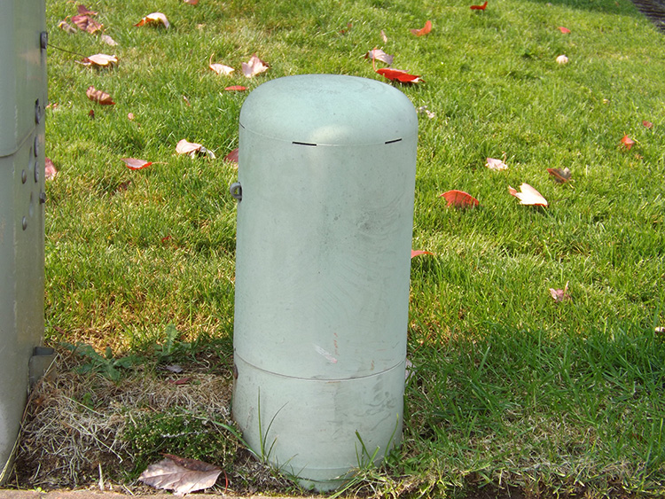
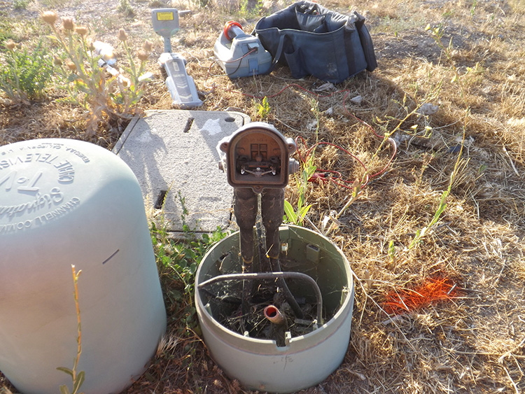
The only exception here is with the residential pedestals which are very small and dome shaped. These are used for the tap between the main cable and the service drop. The tap is any pedestal that feeds service to the house. It also blocks any AC current on the cable from reaching the house. So, the tap blocks 60 Hz current, but allows the communication signals at higher frequencies to pass downstream.
At any point in the line a coaxial cable may be spliced in to a 3 or more separate cables at a splitter. These are within pedestals, or aerial, and easy to recognize.
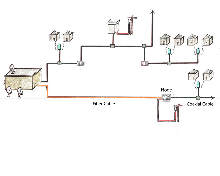


Any cable TV system that originates at the headend as fiber is referred to as an HFC architecture (Hybrid Fiber Coax), and these are probably the most common cable TV architectures today.
Once fiber optic cable became available in the 1980’s, then the cable TV operators began adding fiber to their plant, usually as a trunk line to carry the signal out to the neighborhoods. The longer the fiber cable, the fewer number of Power Supplys and amplifiers that would be needed farther downstream.
A cable TV fiber cable will eventually be altered to coax at a node. Nodes are the same size and shape as amplifiers, but there is a solid distinction. A node will have a wavy vent pattern, while amplifiers have straight vent patterns.
Today, Cable TV plants are typically about 80% aerial, and 20% buried, but that is for the overall plant. In newer residential areas the vast majority, if not the entire plant will be buried.
All coaxial cable is constructed in the same basic format, a conductor inside of a conductor, with a dielectric (non-conductive) material between the two. There is a difference in size depending on how far upstream the cable is. The cables closer to the head end will have a larger internal conductor, and therefore have an overall larger size than those downstream.
All buried coaxial cable is insulated with black poly, which is a thin jacket around the cable to help prevent damage from the contact with the soil. Aerial coaxial can be jacketed, or unjacketed. Two coaxial cables on a pole line may sometimes appear to be two completely different utility types. While a jacketed coax will be black and appear much the same as a fiber cable, a coaxial cable that is not jacketed will be very noticeable because of the outer aluminum.
Cable TV companies are more concerned about tampering with their facilities than other utilities. All utility operators are concerned with vandalism, but cable TV operators are also far more prone to theft of service because it is easy to connect a coaxial cable onto a splitter.
All cable TV pedestals have a locking mechanism, and they are produced in different configurations. The basic pattern is a cloverleaf shape, but it may be a 5 leaf, 6 leaf, 8 leaf, or some other pattern. Anyone working as a contract locator, or directly for the cable TV company will of course be supplied with the proper tool for that particular plant, while SUE locators will usually have to contact the cable TV operator to gain access. Many pedestals are also padlocked to prevent tampering from someone who may have found a cable TV wrench on the ground, or purchased one off the internet.
A supertrunk is a coaxial cable placed between a head end and a remote head end. In this way only the main head end is receiving satellite signals, while the remote head end serves as more of a distribution point. This cable may be placed along with a trunk coax in the same route.
Fiber cables are also commonly ran in redundant circles around an entire populated area, connecting to multiple remote head ends, and allowing for continued service even during a fiber cable damage. The result of this is that it is not surprising to see a coax and fiber ran together, or even strapped together, or two coaxial cables ran together, and both owned by the same cable TV company.
AMPLIFIER
CATV feature that contains coaxial cable in and out. They can be aerial or ground mounted in a pedestal. They have straight vents on the sides to dissipate heat.
CATV
Originally this acronym stood for Community Antenna Television, then Community Access Television. Today it is expressed as simply Cable TV.
DROP
The service line to the house or building. Commonly used in both cable TV terminology, as well as telephone.
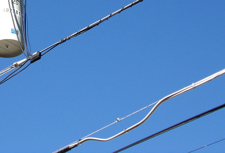
EXPANSION LOOP
The drooped portion of a coaxial cable in an aerial placement. They allow for cable expansion during major changes in atmospheric temperature.
FEEDER
In cable TV terminology, the coaxial cables that are downstream from a Bridger amplifier. Comparable to “distribution cable” or “main line” in other utilities.
HEAD END
The center point of a cable TV operation. Usually a small building with multiple satellite dishes. Also known as an MTC (Master Telecommunications Center).
HFC (Hybrid-Fiber Coaxial)
A cable TV architecture that uses both fiber optic cable and coaxial cable.
NODE
A CATV device that transfers optical fiber transmission to electromagnetic coaxial transmission. They will have one fiber cable going upstream, and a coaxial cable going downstream. All nodes also have an electric power feed. Cable TV nodes are very similar in appearance to Cable TV amplifiers, but nodes have a wavy vent pattern instead of straight.
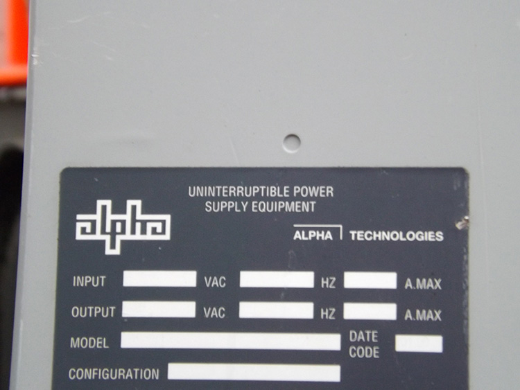
POWER SUPPLY
In Cable TV systems this refers to a medium sized cabinet that has electric power in, and electric power out, but on a coaxial cable instead of a power cable. A power supply puts a 60 Hz current on to the coaxial cable throughout the system. Some power supplys also have a natural gas service as a back-up.
SPLITTER
A cable TV device for splitting coaxial signal in to two or more separate signals, sometimes many more. Usually contained within a pedestal, or can be aerial.
SUPERTRUNK
A coaxial cable that is placed between two different Head Ends.
TAP
In cable TV systems, the connector where the drop service is attached to the feeder cable. They are contained inside of small domed shaped pedestals, or may be an aerial connection.
TRUNK
In cable TV terminology, the coaxial cables that are placed between the Head End and the Bridger amplifier.