
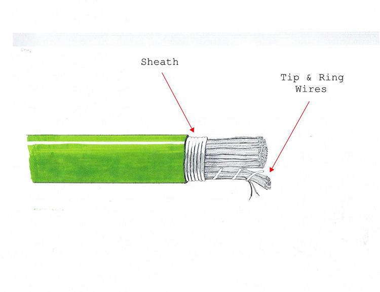
From 1876 to 1888, there were a number of different types of cables used, and no real format to them. In 1887 a conference was held between a number of the different companies to establish standards. So, 1888 brought the first telephone standards. For the telephone cables this meant a pair of conductive wires for each phone service, the wires were 18 gauge copper and twisted around each other, the start of the “twisted pair copper cable”, which is still the format for telephone cables today. The outside sheath was made of a lead/tin alloy, and the insulation was made of oil-soaked cotton. The biggest cable was a 52 pair. In 1891 the insulating material was changed to strips of waxed paper.
These lead cables were identified only by their pair count and gauge. A cable marked as “51-17” was a 51 pair cable, with 17 gauge conductors. A 26 pair cable with 26 gauge wire would be listed as “26-26”.


Beginning around the late 1940’s, that outer lead was now removed and replaced with various plastic coverings. The paper insulation remained, so the name “paper cable” is often used to identify them. Paper cables have a paper mulch insulation of the tip and ring wires, an outer polymer (plastic) jacket, and just like lead cables they were “air core”, meaning they had no filled interior. Paper cables are also commonly referred to as “pulp cables”, but they mean the same thing. These paper/pulp cables were manufactured from about the late 1940’s up to 1958.
Paper cables were still used inside of the Central Office. The fact that they were prone to moisture damage was not a problem because they were contained only in the dry vault area of the CO.
In 1958 came the PIC cable, Polyethylene Insulated Cable. Many technicians also refer to them as Plastic Insulated Cable. For the first time there was a true separation of sheath and jacket. The inner sheath was an aluminum-steel alloy in a corrugated form. The outer jacket was polyethylene.
PIC cables were also gel-filled. Their interior is filled with a jelly-like substance to prevent serious water damage if the cable is slightly damaged on the outside.
The 25 pair would become the smallest cable. If the pair count is marked as “6”, then it is a 600 pair, not a 6 pair. All larger cables would have pair counts that could be multiplied by 25, such as 50, 100, 200, 600, etc. A few cables are even produced with pair counts of 75, and 175. The largest cable produced was the 2400 pair.
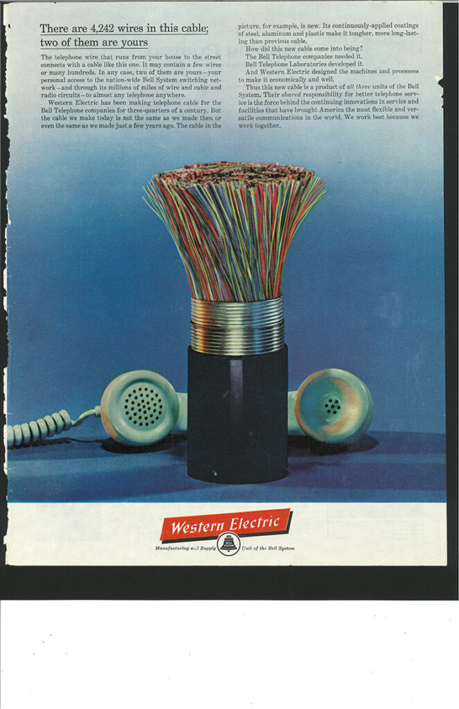
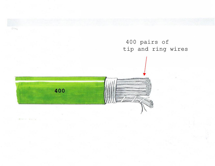
Those pairs are then combined into bundles of 25 pairs, technically known as binder groups. Telephone cables are always referred to by their pairs so there are always twice as many conductors in the cable as the pair count indicates – a 200 pair cable has 400 conductors, but is always called a “200 pair”. Those pairs are then combined in to bundles of 25 pairs per bundle, so a 200 pair cable has 8 binder groups.
Overall, phone cables have had a vast number of changes over the years, and phone cables are often identified by their use (the “C” codes) instead of their type, but you can actually simplify most phone cables into just four basic groups: Lead, Paper, PIC and T-Screen. They first three are all “twisted pair copper cables”, but there are several differences between them which can be summarized here.
LEAD – Produced from 1888 to the late 1940’s. The insulation material within the cable was a mulched paper (pulp) which insulates every tip and ring wire, the outer sheath/ jacket is lead including the splices. Many lead cables are now pressurized (with an accompanying air hose), and lead cables are usually found only in duct runs, though there are exceptions. On phone prints they are usually indicated in the old number code, such as (51-22 or 51-26). The first set of numbers was the pair count, while the second set of numbers was the gauge of wire. Some of them may be indicated on the prints in the newer 4-letter code starting with 2-Xs and always ending with the letter “L”, such as XXTL. Lead cables do not have any printing on the outside of the cable.
PAPER – Also known as PULP cables. They were produced from the 1940’s to about 1958, though there were a few still being installed in outside plant (OSP), up to the early 1960’s. They have the same basic construction as lead cables, but with a plastic outer jacket instead of a lead sheath/jacket. They have colored insulation on the tip and ring wires, but it is not an individual color coding. Most paper cables are now pressurized (with an accompanying air hose), and paper cables are usually found only in duct runs. Paper cables were the first to use the 4-letter code, and on phone prints they are shown with the 4-letter code, and usually with the letter “D” in the second position, such as HDBF or ADKA
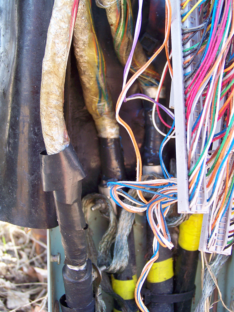
PIC – Polyethylene Insulated Cables have been the only phone cable since 1958. Their tip and ring wires all have individual color coded plastic insulation within a specific bundle, so all 25 pairs in a bundle have individual color codes, then each bundle tape has a different color code. PIC cables are the only phone cables that have plastic insulated conductors, though you would typically never see the exposed interior of a lead or paper cable anyway. PIC cables have a steel/aluminum sheath around the conductors, and a polyethylene outer jacket. This is referred to in the 4-letter code as though the sheath and jacket were one and the same, so they are labeled as having a sheath of aluminum/steel/polyethylene, or with an acronym for the three such as ASP.
PIC cables are produced in pair counts of 25, so their sizes are 25, 50, 75, 100, 200, etc.
PIC cables are indicated on phone prints with the 4-letter code, such as ANMW. All modern cables are PIC cables and they are found in duct runs, phone pedestals, AP’s, aerial cables, DSL cabinets, and connecting to load coils and repeaters.
T1 – T-Screen – T-Screen cables are used in the T-1 through T-3 systems. They are produced in pair counts of 26, 54, 106, and 210. They have some similarities to PIC cables except that their tip and ring wires are not twisted together, but separated, all tip wires are bundled together, and all ring wires are bundled together. T-Screen cables are very noticeable in pedestals because of the aluminum wrap around the two bundles
Both lead and paper/pulp have an inherent weakness in outdoor applications. Any damage or excessive wear on the sheath can easily allow water inside the cable. Although both lead and paper cables had paper insulation, the paper itself was never the true insulation. It was the air in and around the paper that provided the insulation.
PIC cables and T-Screens have a gel-filled insulation, so when PIC cables were introduced, it then became the standard to refer to the lead and paper cables as Air Core Cables. The gel-filled insulation of PIC cables naturally prevents moisture from entering the cable. However, the paper/air insulation not only can not prevent moisture, it actually attracts moisture if it is damaged. That paper/air insulation reacts like a paper towel and soaks up any moisture touching the cable.
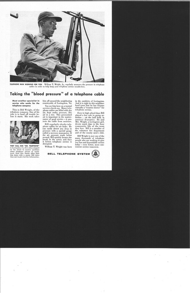
The answer was found in forcing dry air into the cable at different points. An air dryer/compressor forces air into a small air hose which runs the length of the cable. At various points the air hose will connect into the cable. This way the air is not forced in at just one end of the cable, but instead at different areas of the cable which is much more effective. As long as the air pressure exceeds the psi of surrounding water, which is usually no more than 5 psi even in 10 feet of water, the air will keep the water out. Since phone companies want to ensure that the cable stays dry, even in the wettest season of the year, most will use a 7.5 psi as a standard minimum pressure.
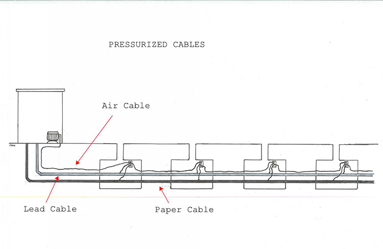

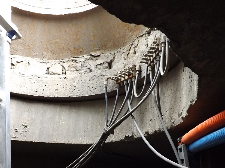
All of the air cables must connect to a dryer/compressor somewhere along the line. This is usually at the CO, but on rare occasions you may come across a dryer/compressor along the duct run, and probably very near a manhole lid, where there will be an aboveground dryer/compressor, probably operated by a generator. The compressor is set to kick on when ever the pressure drops below 7.5 psi. This is of course not a lot of pressure, but enough to do the job. The air hose will come from the compressor into the manhole, where it will make its’ first connection onto the cable. Then it will follow the cable through the duct run, making more intermittent connections as it goes. The connection from the air hose to the cable is called a manifold, though it actually looks more like a bicycle tire valve.
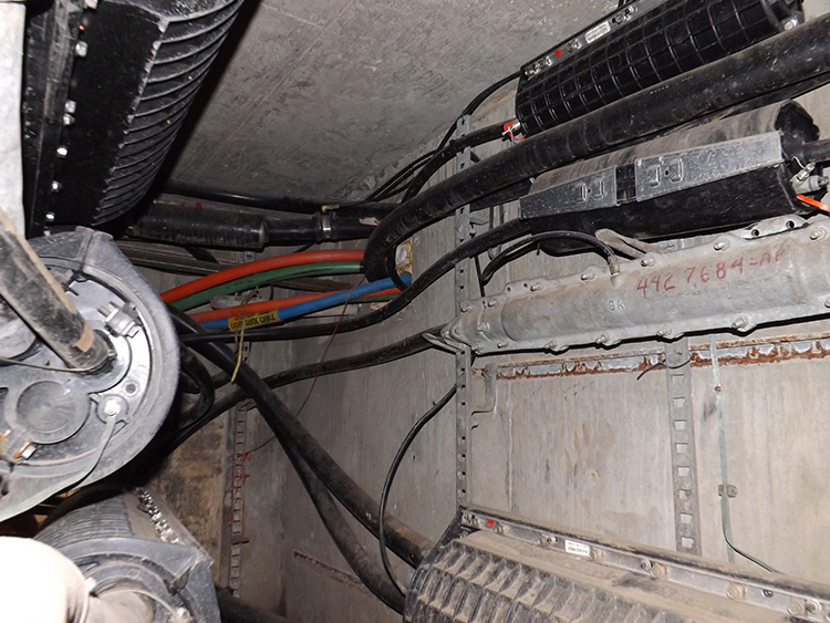
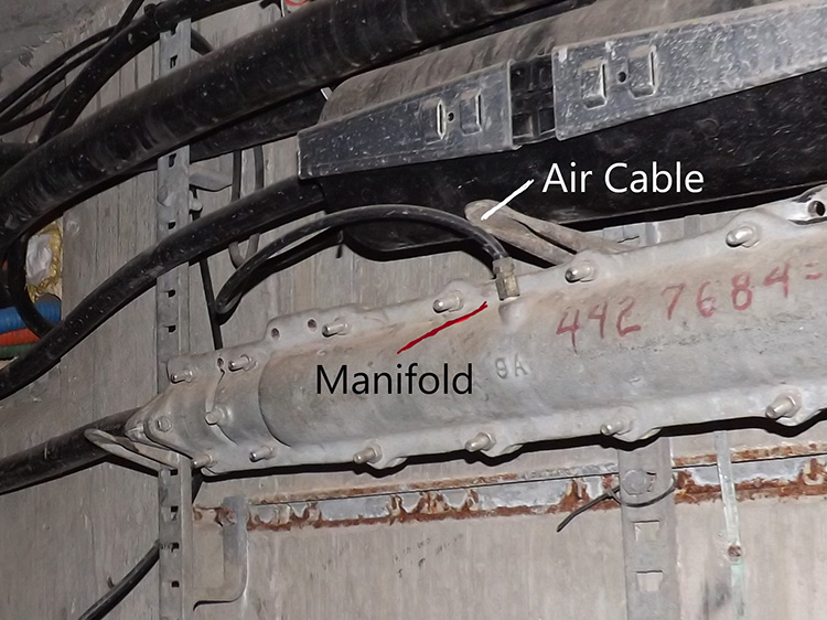
The air hose is also quite commonly referred to as an “air cable”. Neither term is really accurate since the “air” being pushed into the hose is more nitrogen than oxygen. All of the older air hoses were strictly made of rubber, but later on they were produced with an aluminum inner sheath.
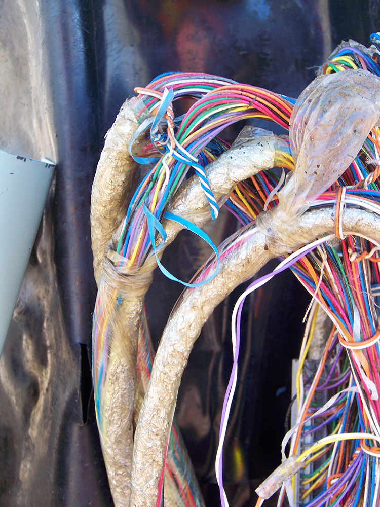
Since telephone cables can be quite numerous in a pedestal or cabinet, it is very helpful for the phone technicians to know which cable is going which way. The answer was for technicians to begin a color code for each direction. Then they could simply wrap some colored electric tape around the cable within the cabinet, or possibly used some colored plastic ties, and more easily know for sure the direction of the cable. This system has been used quite often, mainly by telcos that were part of the Bell System, but it is not a guarantee of direction.
NORTH – ORANGE
EAST – GREEN
SOUTH – BROWN
WEST – SLATE
The color compass can be easily remembered using the phrase Only Good Boys Succeed. Starting at north – and going clockwise: O – G – B – S.

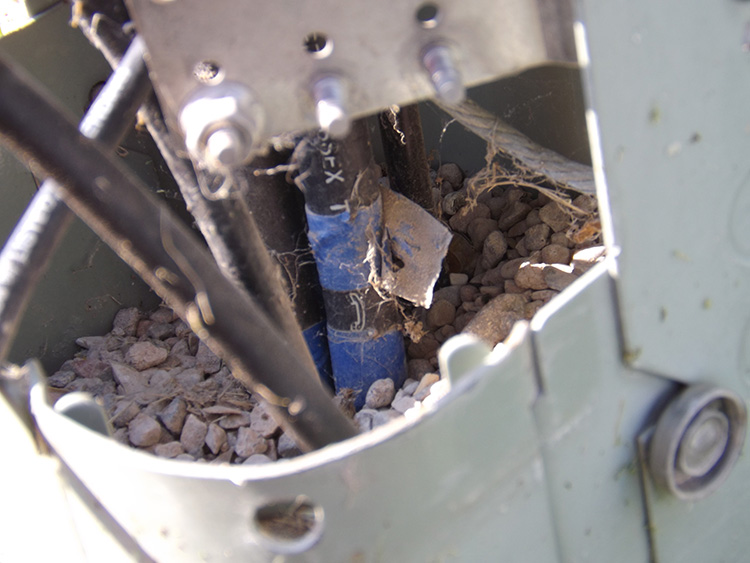
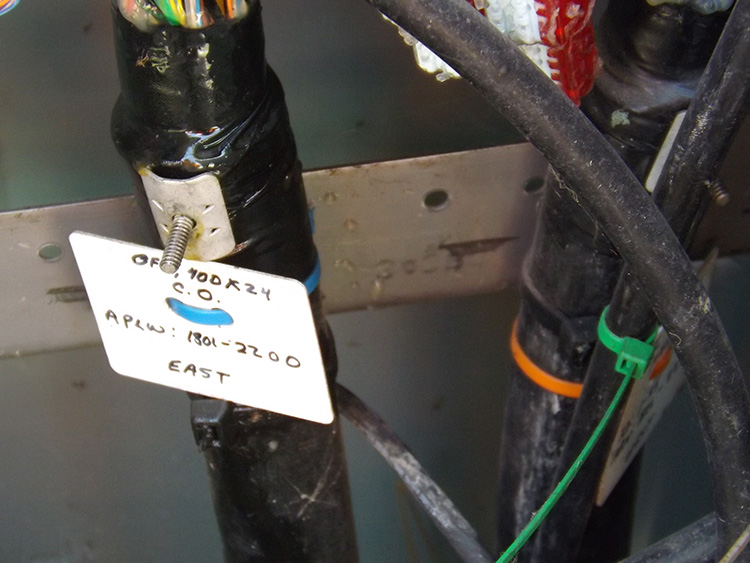
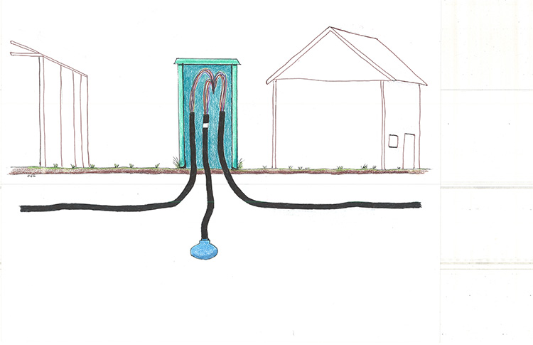
There are also two more colors used to give information on cables. The color blue indicates the cable that is headed towards the Central Office. The other color is white and indicates the cable that connects with a load coil. That load coil may be aboveground or belowground.
NORTH – ORANGE
EAST – GREEN
SOUTH – BROWN
WEST – SLATE
Central Office – Blue
Load Coil – White
THE NUMBER CODE
Lead cables 1888- c.1949
The original coding system for telephone cables was used on phone prints but not on the cables themselves. They consisted of two sets of numbers, such as 26-22. The first number indicated the pair count, while the second number indicated the gauge of conductor used. In this system a 26-22 was a 26 pair cable with 22 gauge (size) conductor wire.
Wire gauge is actually opposite of what it might first seem – the higher the gauge number, the smaller the diameter. Over the years the cables were often produced with smaller and smaller tip and ring wires, and this shows in the increase in number for the wire gauge.
1st set of 2nd set of
Numbers*- Numbers-
Years Produced Pair Count Gauge Sheath Insulation
1888-1891 52 18 lead/tin oiled cotton
1891-1892 52 19 lead/tin waxed paper
1892-1895 100 19 lead/tin waxed paper
1895-1896 152 19 lead/tin waxed paper
1896-1896 180 19 lead/tin waxed paper
1896-1901 208 19 lead/tin waxed paper
1901-1912 303 19 lead/tin waxed paper
1901-1902 404 22 lead/tin waxed paper
1902-1912 606 22 lead/tin waxed paper
1912-1958 26 22 lead/tin/antimony waxed paper
1912-1958 51 22 lead/tin/antimony waxed paper
1912-1918 303 19 lead/tin/antimony waxed paper
1912-1930’s 909 22 lead/tin/antimony waxed paper
1914-1930’s 1212 24 lead/tin/antimony waxed paper
c.1915-1958 26 & 51 24 lead/tin/antimony waxed paper
1918-1930’s 455 19 lead/tin/antimony waxed paper
c.1925-1958 100 -1200 24 lead/tin/antimony waxed paper
1930’s – 1958 100 – 900 22 lead/tin/antimony waxed paper
c.1940-1958 26-51-100 26 lead/tin/antimony waxed paper
c.1940-1958 26-70-100 19 lead/tin/antimony waxed paper
1942 54 19 lead/tin/antimony waxed paper
——————————————————————————————————————–
1950’s 26 – 51 – 400 22 alum/poly waxed paper
1950’s 2400 26 alum/stl/poly waxed paper
This code is used on phone prints, and has also been stamped onto the modern PIC cables. The vast majority of cables using the 4-Letter code are PIC cables.
Paper cables have been labeled with the 4-letter code on phone prints, but not on the cables themselves.
Also, many old lead cables have been relabeled on some phone prints using the 4-letter code, but always beginning with the letters “XX”.
With the 4-letter code, the pair count will always follow the code, such as: ANMW – 2, but if the number is only a single digit then it is an indication of a number that should be followed by 2 zeros. Therefore, an ANMW-2 indicates a 200 pair cable.
1st Letter 2nd Letter 3rd Letter 4th Letter
Cable Design Conductor Insulation Conductor Sheath
A – PIC waterproof B – Polyethylene PVC J – 13 gauge/copper A – Alpeth (aluminum &
Or Pulp air core Polyethylene)
B – PIC air core C – Foam skin / H – 16 gauge/copper C – Stalpeth (steel, alum- Polypropylene inum & polyethylene)
C – PULP or High D – Paper Cable C – 17 gauge/alumin D – Lepeth (lead &
Waterproof Polyethylene)
D – PIC Steelpeth or F – Foam skin / Dual B – 19 gauge/copper E – Polyethylene
Ductpic types expanded Polyolefin Jacketed lead
K – Screened Core G – Solid Polyolefin D – 20 gauge/alumin F – Polyethylene jacketed
L – Low Capacitance H – Solid Polyethylene A – 22 gauge/copper G – PAP (polyethylene
Aluminum)
M – Low Capacitance J – Solid Polypropylene F – 22 gauge/alumin H – PASP
Jelly filled
X – Lead Cable* K – Solid Polypropylene M – 24 gauge/copper J – TOLPETH J
L – Dual expanded K – 24 gauge/alumin K – TOLPETH K
Polypropylene
R – Dual expanded T – 26 gauge/copper L – Lead Cable
Polypropylene
N – Dual expanded W – 28 gauge/copper M – Alvyn
Polypropylene
X – Lead Cable* N – Stalvyn
P – Reinforced self-
support
R – ARPETH
S – Self-supporting
T – ARPAP
U – ARPASP
V – STEALPETH
W – ASP
X – Abandoned **
Y – Bonded ASP
Z – Bonded STALPET
(*) Any cable with a 4-Letter code that begins with two X’s is a lead or paper cable, and almost always a lead cable; such as XXTL.
(**) When a PIC cable is abandoned, the last letter is sometimes changed on the prints to an “X” indicating that it is no longer in use, such as BKTX.
In addition to the 4-Letter code, there may sometimes be another 2-Letter code shown after the pair count, such as: BKTA – 200 – BT. The last two letters, BT, indicate that this is an armored cable. The PIC cables were much more susceptible to damage so some high-profile PIC cables will have an armor coating.
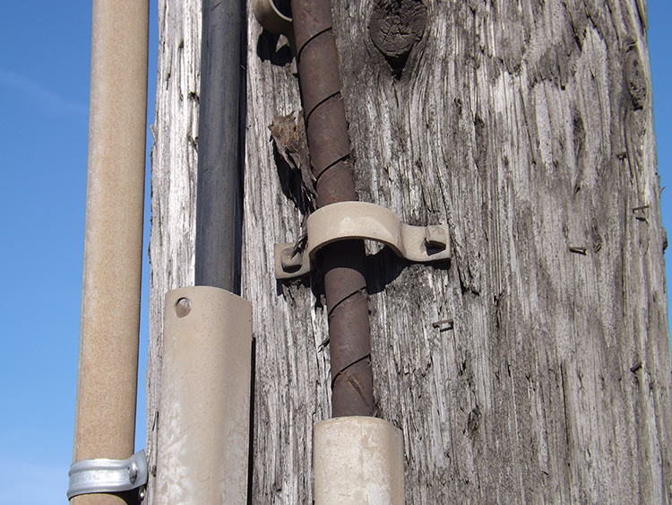
Gophers can easily chew through a PIC cable. This doesn’t happen very often, but it does happen. Today most cables that run up a pole to an aerial line are protected by plastic or metal conduits, known as riser guards, but the conduit never covers the entire cable, and these were sometimes being chewed on by squirrels or damaged by vandals. Certain buried cables that were used for airports or military bases could not afford to have the lines go down just because of a hungry gopher. The armored cables were created to provide these high-profile services with all possible protection. Below are the 2-letter codes for the 4 different types of armored cables. The UM cables are commonly used for military installations.

AT – Aerial Tape Armor
BT – Buried Tape Armor
MP – Mechanical Protection
UM – Unsoldered Mechanical Protection
These might be called “C” codes because each of them consists of a number, or numbers, followed by the letter C, but actually the “C” simply means code. This idea came from the municipal water departments who had originally devised a series of C-codes for water pipes and activities. Just like water pipes, these phone C-codes can in some cases be related to the type of material, but their main purpose is to identify the actual use of the cable, such as an aerial cable running pole to pole.
This “C” code was applied to fiber lines when they were first being installed in the early 1980’s, and was partially meant to quickly identify fiber lines from the old copper lines. However, the anxiety over the possibility of damaged fiber led the phone companies to make sure the fiber was clearly identified on the prints with something more than just a simple “8C”.
Many telephone prints will show only one set of codes or the other. They may show only the 4-letter code, sometimes with just an additional “B” for the buried cables, while more simplified prints may only show the “C” codes, probably with “F/O” for the fiber lines. Most phone prints that have been modernized to a cad file will probably show both codes so the viewer can easily identify both the use of the cable, and its’ material and gauge.
4C – Conduit (may be an empty conduit for future use)
5C – Cable in Conduit (cable was pulled through the conduit as soon as it was placed in the ground)
6C – Submarine Cable (placed under water such as a lake or river)
8C – Fiber Optic Cable
12C – Aerial Cable
14C – House Cable
25C – Trunk or Toll Cable
45C – Buried Cable
52C – Aerial Cable
62C – Cable inside building
85C – Buried Fiber Optic Cable
812C – Aerial Fiber Optic Cable
825C – Trunk or Toll Fiber Cable
845C – Direct Buried Fiber Cable