GROUND PENETRATING RADAR – GPR
By far, the most common secondary instrument today is Ground Penetrating Radar (GPR). Most manufacturers offer detailed courses on the use of GPR with field exercises which should always be mandatory for anyone first starting out with the instrument. This page is only meant as an introduction to GPR in order to make the class easier to understand. It is very advisable for any operator to be properly trained in its use in order to achieve the proper results. Too many operators have come to the conclusion that “those things don’t work” simply because they never received proper training.
The first thing to know about GPR is that it is completely dependent on the permittivity (the ability of the soil to hold an electric charge) of the soil, and the permittivity of soil depends on the amount of electrolytes in that soil. Sand has very few electrolytes, while clay soil is heavy in electrolytes. Common top soil lies in the area in between.
SOIL SUITABILITY MAPS
What this means is that a GPR can detect buried utilities with clear images and at substantial depths as long as the soil is low in electrolytes – sandy. At the other end of the spectrum, clay soil can sometimes give completely negative results.
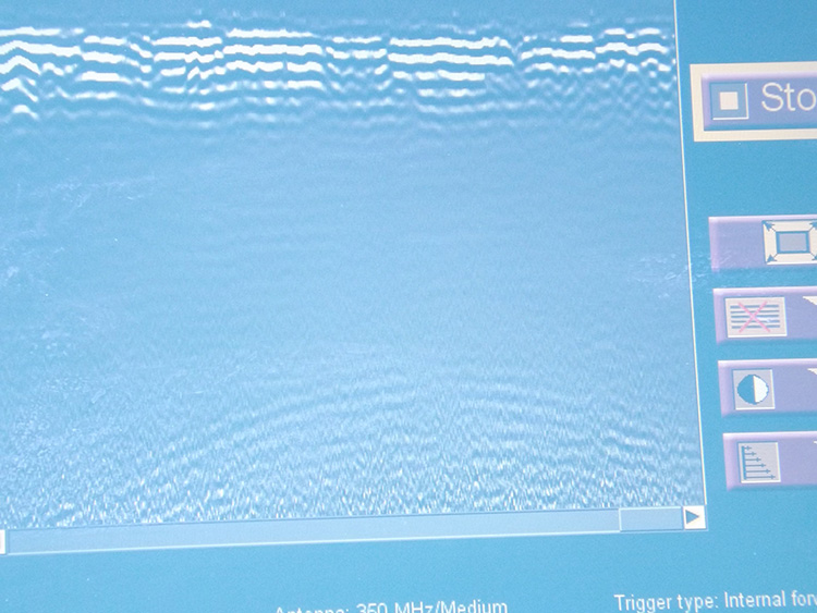
The problem with electrolytes is that they absorb the energy of the radar. Much like regular radar, GPR is sending energy in to the ground, and then detecting that signal return to the GPR unit. But electrolytes, salts and acids, absorb the energy so the signal does not return to the GPR and the screen shows only even lines.
WHAT IS BEING DETECTED?
What this means is that a GPR can detect buried utilities with clear images and at substantial depths as long as the soil is low in electrolytes – sandy. At the other end of the spectrum, clay soil can sometimes give completely negative results.
The problem with electrolytes is that they absorb the energy of the radar. Much like regular radar, GPR is sending energy in to the ground, and then detecting that signal return to the GPR unit. But electrolytes, salts and acids, absorb the energy so the signal does not return to the GPR and the screen shows only even lines.
FREQUENCY
Like all electromagnetics, the lower the frequency, the farther the signal will travel. A GPR unit that is 400 MHz will be good for detecting shallower objects with clarity, while a 200 MHz unit will be better for detecting deeper objects. Since GPR is used for many different types of underground survey, there are a variety of instruments and frequencies. The range of 250 MHz to 300 MHz is often thought to be the best for detecting utilities.
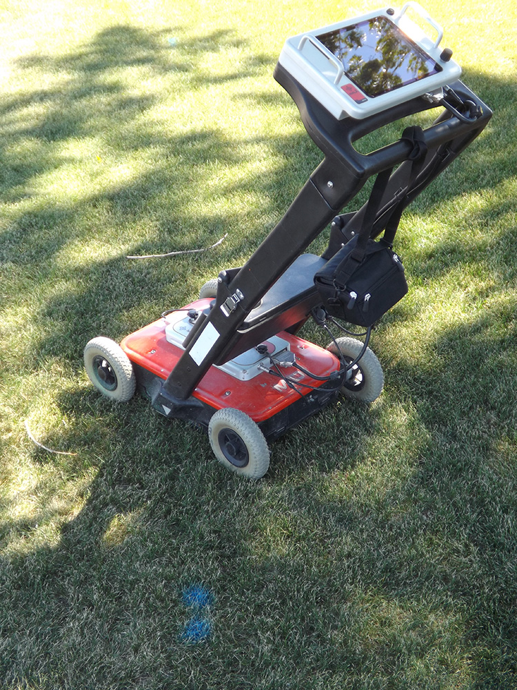
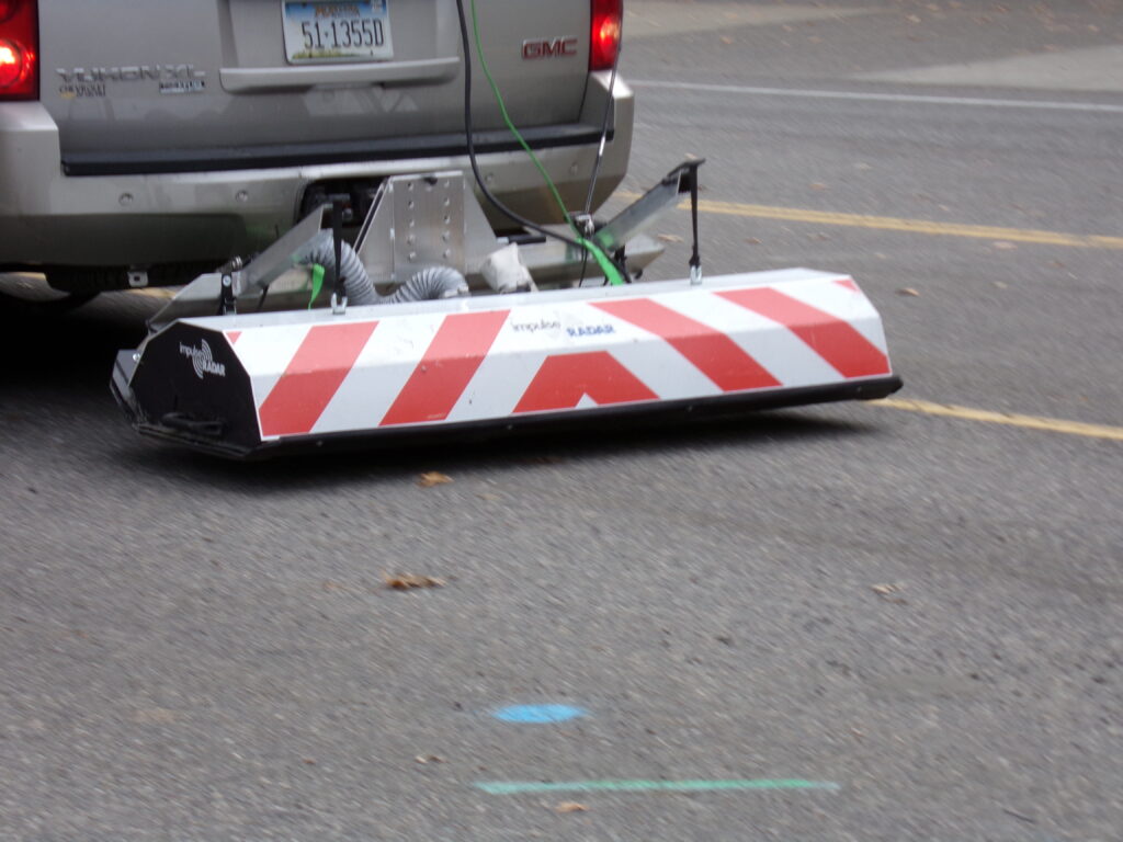
GPR units may not resemble each other at all. Some are handheld, and others are meant to be pulled behind an automobile.
SIZE TO DEPTH RATIO
There is a correlation between the size of the object and the depth at which it can be detected. Many operators use a general rule of thumb that every inch in diameter of the utility equates to about 24 inches of detectable depth. In other words – a 4-inch pipe may be detectable at possibly 8-feet deep.
That is an easy ratio to remember, but to be more precise, the common ratio is 15-20 :1 depth to diameter. This means that a utility line 1-inch in diameter may be detectable at roughly 15 to 20 inches in depth. Therefore, a 4-inch pipe may be detectable at 60 to 80 inches deep (5 feet to 6.5 feet)
Remember this is only a general rule of thumb and depends on a number of factors. Yet, it does illustrate the point that very small diameter utilities are less likely to be detected than larger pipes. However, remember that a utility line which is nonconductive, and therefore needs to be traced with a GPR is most likely a main line pipe, and most likely at least 4-inches in diameter if not larger. A small fiber optic cable is either placed with tracer wire, or has a center conductor or a sheathed conductor, and can be located out easily with a PCL. Why use a GPR to search for a small fiber cable? Use the PCL and you can trace it out much faster.
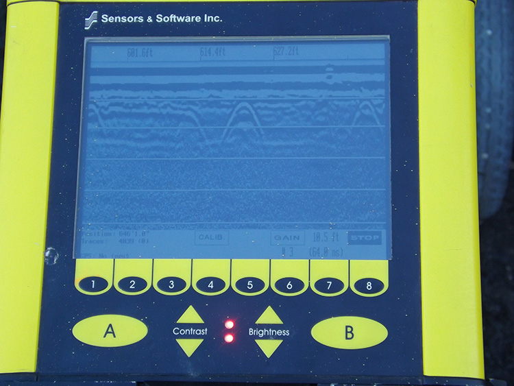
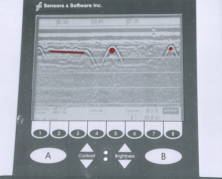
HYPERBOLA
Many technicians are confused when first trying to operate a GPR, usually because they have a long history of operating a PCL and are trying to correlate the image on the GPR screen with what they are used to. GPR can be used to follow a utility line, but that is rare. The standard method is to not follow the utility – but to cross back and forth over the utility. This will provide the most distinctive signal.
In other words, if the utility line is running north/south – then you push the GPR in an east/west path. Cross the project area, then move up, and cross again. You continue this procedure as many times as necessary. So, you are not tracing out the utility, but crossing the project area, and collecting points or “hits” on the utility. The information you are collecting is in pieces, but this provides the best method of making the utility visible.
The actual image you will see on the screen is a hyperbola, an image that resembles an upward shooting comet. That is not what most people would expect. We expect to see the utility – a pipe – a cable – a conduit – something round. Yet, that is what we are seeing, but we are only seeing the very top of that pipe/cable, the very top of that “comet”. The image shows a widening flare because of the weakness of a radar signal. GPR is not exactly like standard radar, but it is a reflection of radar waves, and remember, a person watching a radar screen does not ever see the shape of the airplane, only a blip on the screen.
GPR is actually a little more distinctive because we can see that rounded portion at the top of the hyperbola, and that does tell us that what we are detecting is a round object. Flatter objects such as a duct run with concrete on top, will show a flatter image on the screen.
PIPE MATERIAL
While GPR can detect any pipe material, some are better than others. Clay pipe in clay soil may not have enough differentiation as AC pipe. Though of course in very clay type soil, you will be less likely to detect any pipe.
Metal pipe is the one that really stands out. The radar waves can penetrate all types of material, but not metal. When passing over a metal pipe almost 100 % of the signal will be reflected back to the GPR unit. This tends to produce a very solid hyperbola. This is true with iron, steel, or even lead pipe.
On the other hand, plastic pipe is easily penetrated and the signal reflects inside of the lower portion of the pipe just as it does with the top portion. The result is what appears like an echo image on the screen. Besides the top hyperbola, there will often be additional hyperbolas one directly on top of the other, though fainter than the top hyperbola, and the entire image will probably be slightly fainter than it would be if it were steel.
So, metal pipe usually produces a more solid image, while poly pipe usually produces an echo image. This is also dependent on depth, so the deeper the pipe, the less likely the material differences will show.
GHOST IMAGE
A common image on the screen which is usually misinterpreted is a very wide circular shape. This is not a hyperbolic shape, but a true half circle, and usually extends from one side of the screen to the other. There have been utility pipes constructed of an enormous size, but those are rare. When you see that circular shape across the screen, do not think that you have just come across a 30-foot diameter pipe. Look up instead of down. You are almost certainly crossing under a metal canopy of some kind or even a tree canopy. This can also happen when the only thing above you is a traffic signal post with the regular extended arm. One way or another, there is something above you that is causing this phenomenon. It is impossible to force radar waves downward with absolute completeness. Some of those radar waves will always be going upward, and when they hit an upper object, they will return downward, and register on the instrument in a wide circular pattern.
CLOSE TO THE GROUND
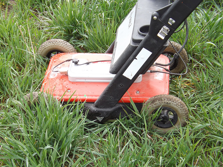
An important issue with GPR is to keep the unit as close to the ground as possible. Even if the unit were only sitting a few inches above the ground, the radar is going to reflect off of the surface of the soil instead of penetrating it. This is why GPR units have plastic skid-plates on the bottom. The unit functions best when being almost dragged along the ground.
WET OR DRY
Some locating instruments are rather simple, such as a magnetometer. Other instruments are easy to use, yet usually over simplified in their operation, such as a PCL.
GPR is neither one. GPRs are designed to be operated by geophysicists, however, this is far from what is happening. The popularity of GPR has ensured that there are more field technicians running GPRs than there are actual geophysicists. As long as the field tech is properly trained, it should not be a problem. But that all depends on the depth of the training, and that they are allowed enough experience with the instrument to get comfortable with it. However, there can still be some issues with that operation, mainly because those issues are not being pointed out.
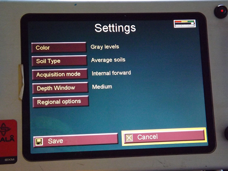
Some GPR units include a wet soil/average soil/dry soil selection on the screen. The result is that many technicians “logically” come to the conclusion that if it rained an hour ago, then switch the unit to wet soil. The issue here is simply that GPR is designed for geophysicists, and to a geophysicist “wet soil” has little to do with whether or not it just rained.
In geophysics nomenclature, “wet soil” means clay soil, and “dry soil” means sandy soil. Clay is referred to as wet because the electrolytes in clay absorb not just radar waves but moisture. Clay attracts moisture, but sand does not.
What this all means is that a recent rainfall can negatively affect the results of GPR, but whether it recently rained or not, if the soil is thought to have a high content of clay, then you should still put the setting on “wet soil”.