ELECTRIC POWER
INTRODUTION
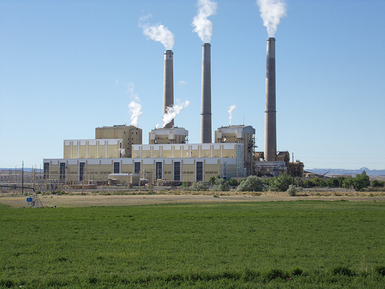
The sources of electrical power can be grouped into four resources: Hydro-power (reservoir); Thermal power (coal, oil, natural gas); Nuclear power (nuclear power plants); and Green power (wind farms, solar panels).
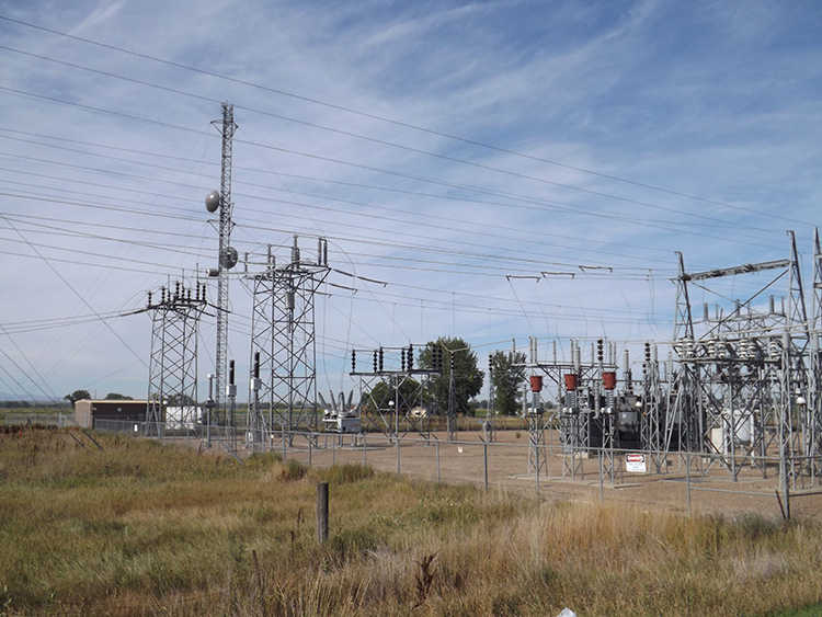
From the source of electric power to the generating station will be the gathering lines. The transmission lines are the power lines on the transmission towers. Transmission power lines were almost always aerial in the past, and commonly on large metal towers. These days they can sometimes be buried in concrete duct structures.
Transmission power can be anywhere from 150,000 volts (150kv) to 760,000 volts (760kv), and on large metal towers.
These switch to a lower voltage on wooden poles, typically about 70kv to 200kv, commonly known as sub-transmission.
From the sub-stations downstream are the distribution lines, and then of course the services.
PHASE: 1, 2, OR 3
Two phase power is very uncommon, but electric power can be single phase, two phase, or 3-Phase. This may be spelled out, or it may be replaced with the symbol Ø. This means that three phase power may be written as 3Ø. All electric current has phase, frequency, and wavelength. Phase could be described as the timing of a single cycle of current. All current on the same power cable is functioning in-phase with itself no matter which point of the cable you are looking at.
The purpose of 3 phase is to provide what could be called more “torque” to the power outlet. This can be compared to the number of cylinders in an internal combustion engine. While most power lawnmowers operate on a single cylinder, automobile engines usually have 6 or 8 cylinders. The lawnmower works properly, but it does not have enough force with the single cylinder to create a “push” to the current. An 8-cylinder engine on the other hand, has each cylinder in a different position at all times. As one cylinder is firing and moving downward to push the crankshaft, another cylinder is just starting its upstroke away from the crankshaft, and the other 6 cylinders are in intermediate positions between the up and down cylinders. Only one cylinder fires at a time, and the others are in evenly spaced positions on the way up or down. Every cylinder is backing up the others by firing while the others are in the non-firing positions.
3 Phase power is roughly similar. The current from each cable “hits” at an evenly spaced time interval. This provides the force to drive large motors. These can be large fans, pumps, and other machines that require more torque in order to operate properly.
Most 3 Phase current is used in manufacturing plants and other industrial areas, but they are also necessary for many businesses that may not seem obvious at first. Even a small car wash usually requires 3 phase for the water pumps. Many residential customers also have 3 phase power to their home. This is usually a homeowner who has certain types of machinery in their home or garage that contains large motors, such as a band-saw. An office building does not necessarily need 3 phase just to operate computers and coffee machines, so it is possible to come across large office buildings that are fed by single phase. If it is a multi-story building, then 3 phase becomes far more likely because a high-rise is more likely to have an elevator and elevators require large motors.
LAYOUT
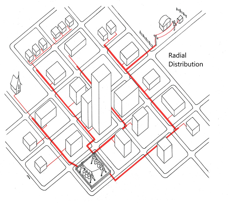
Electric power of course goes from the power sources downstream to the substations. However, the distribution portion of an electric plant is not easy to simplify, because there are three different types of distribution layouts. They are Radial, Loop, and Network.
RADIAL is the layout most people would expect with electric power. The power lines stretch outward across town, carrying less and less voltage until each line comes to an end. Today, this system is still common in rural areas and small towns.
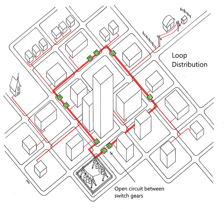
In a LOOP system, the main power lines run in a large circular pattern, returning to the original point. This of course would mean that the electricity is feeding power from two different directions at the same time, and this is technically impossible. However, there is an additional element used here.
In a loop system there are numerous switch gears placed along the route of the main power. At any given moment, one of those switch gears has an isolated set of primary cables. The cables are in the ground, and connected inside the switch gears, yet the primaries are completely isolated with a scissor switch. Only if there is a break in the line at another point, would the scissor switch flip the connections and complete the circuit.
This provides better continuity to the subscriber. If a power line is damaged for any reason, power is almost immediately switched to the other route, so now power is coming from the lines south of your house instead of north.
Loop systems are rather noticeable because of a sizable number of switch gears. Because of their advantage in providing continued service, Loop systems are becoming more and more common.
A NETWORK system is somewhat like a Loop system, but includes more than one large loop. Network systems are common in downtown areas where there can be high load multi-story office buildings, as well as government offices. This system provides the most reliable service possible because there are various routes that the power can be altered to automatically.
CABLES AND WIRES
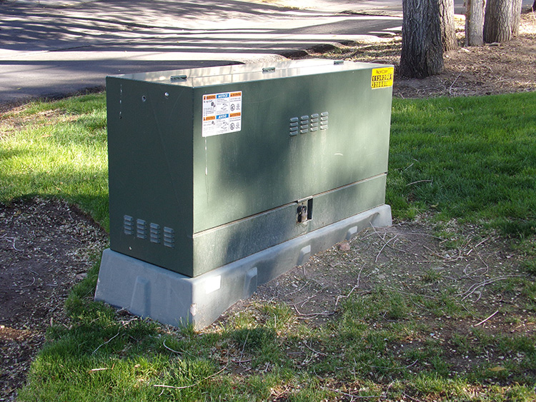
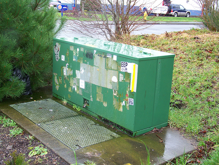
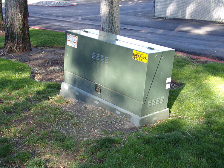
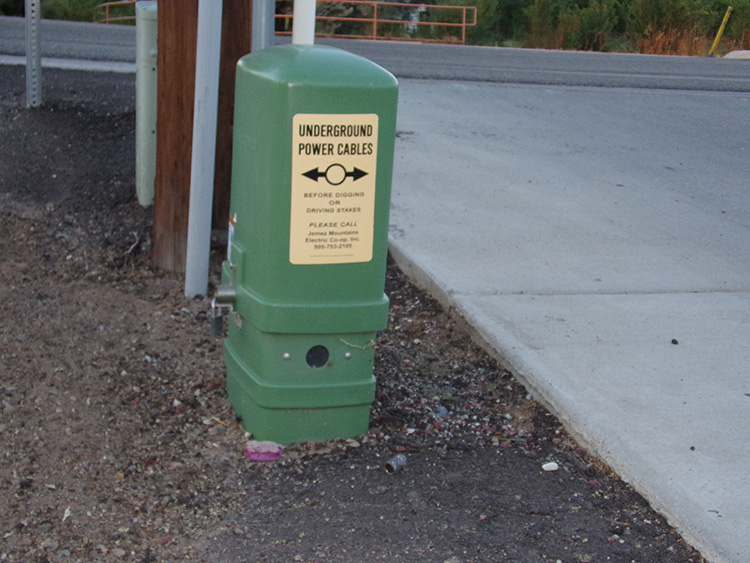
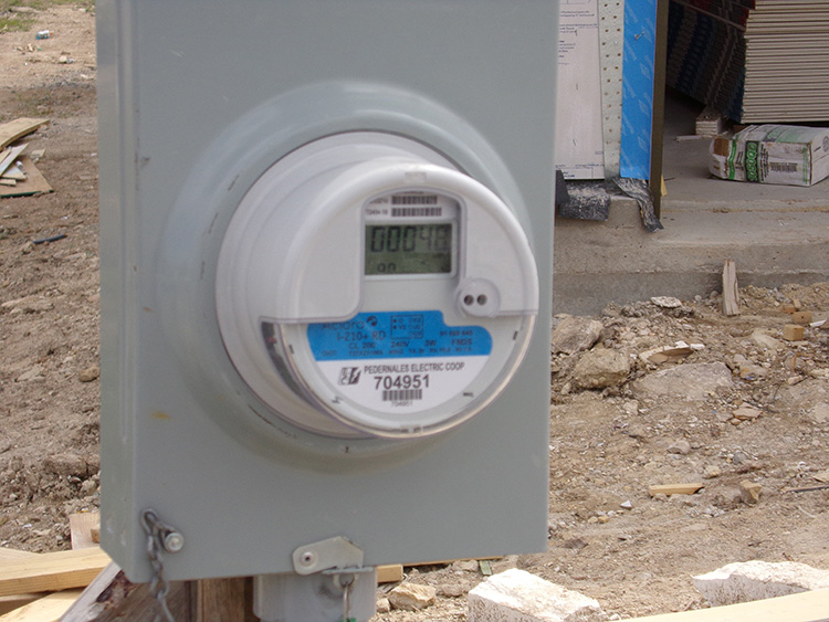
Underground power is rather easy to explain. Primary cables are upstream from a transformer and secondary cables are downstream.
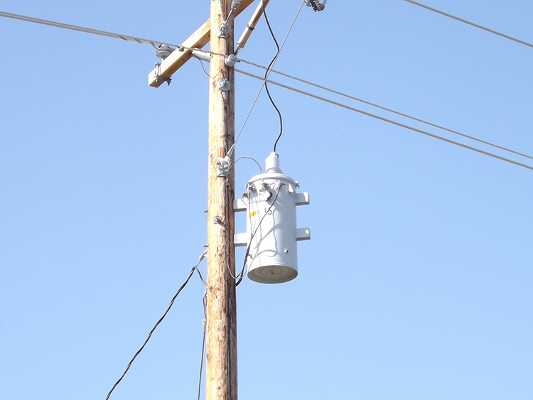
The primary cables will come down the pole, and then may go to a switch gear, or direct to a J-box, or straight to a transformer. No matter which it is, the primary cable or cables will end up at a transformer.
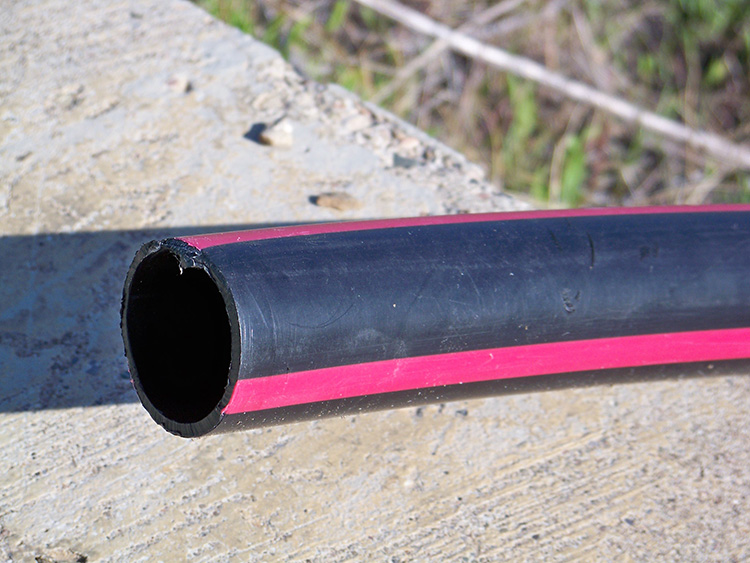
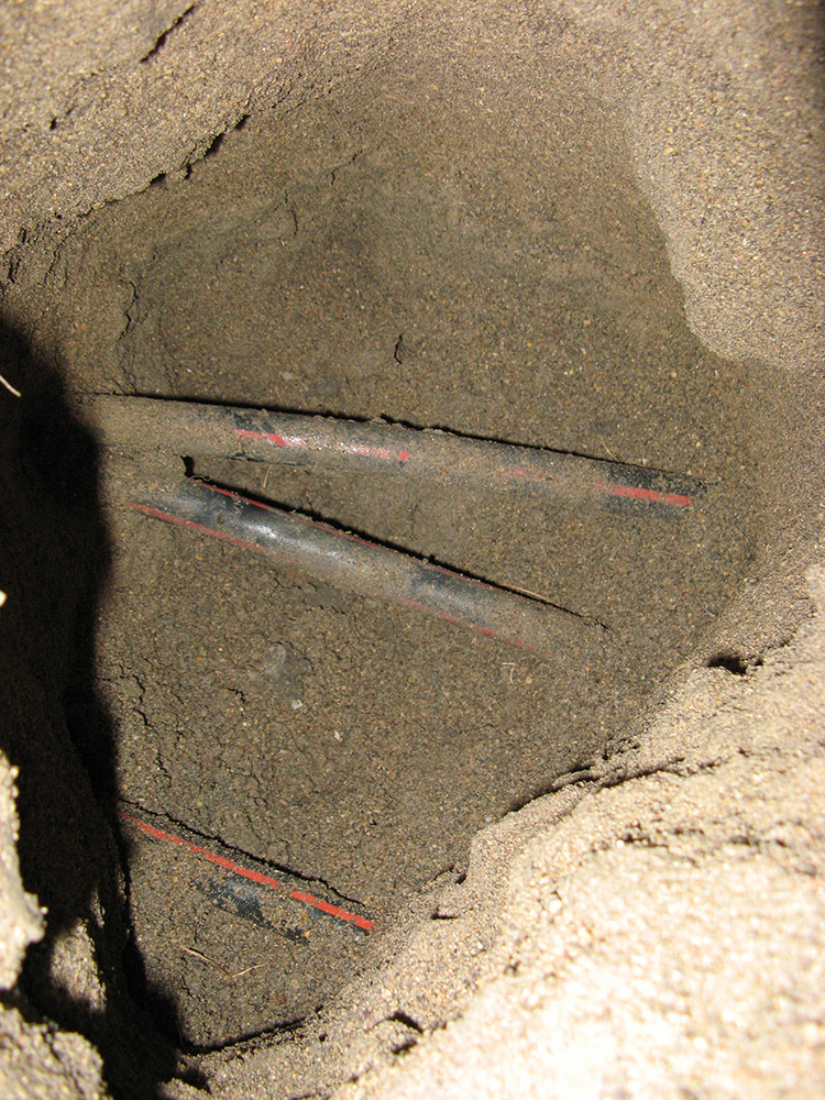
Each cable represents a separate phase of electric power. This is true for both primary and secondary cables. So, if you uncovered a single primary cable in the ground, then that is single phase primary. If you uncovered three secondary cables side by side, then that would be three phase secondary. This is also true for the cables as they are coming down a pole. Three large insulated black cables with a red stripe is three phase primary.
This makes it very easy to identify those insulated cables, coming down a pole, or uncovered in an excavation. The primaries have a thick black insulation with a red stripe. The secondaries are also black insulated, but have a tight insulated jacket like the power cables in the walls of your house.
AERIAL POWER WIRES
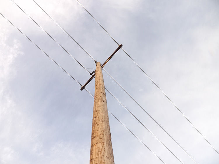
But things change greatly when we are dealing with aerial power. First of all, technically, a cable has multiple conductors, while a wire is a single conductor. Not everyone refers to cables and wires in this way. But it does become an issue when we are looking at aerial power.
All electric current functions in a circuit. In other words, electricity does not actually “feed” your house. It is more accurate to say that electricity “runs through” your house, and the lights and appliances in your house only tap in to that electricity. The current must have a conductive path out to the buildings – and a separate path back again to the sub-station. If we look at just the 2 main conductors involved, the hot wire and the neutral wire, then the electricity is coming in to your house on the hot wire, and heading back to the substation on the neutral wire. Now, admittedly that is a simplified and incomplete description, but it should explain the basic concept of what is taking place. All current operates in a circuit, or it simply does not operate. And a circuit requires two conductors.
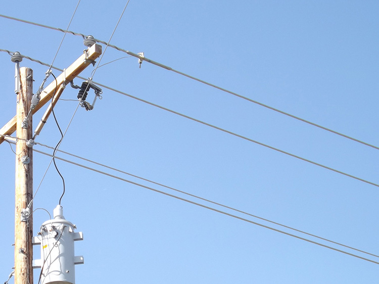
Yet, almost all aerial power is a single conductor. Therefore, a single aerial power wire represents only half of a circuit. This is why we often see two aerial power wires side by side on a pole line. There is two phase power, but it is very uncommon. Those two aerial power wires are almost always going to be a single-phase line of power – one hot and one neutral.
From this we could conclude that 3-phase aerial power would require a total of 6 aerial lines, but that is only with transmission power.
AN EXCEPTION TO EVERY RULE
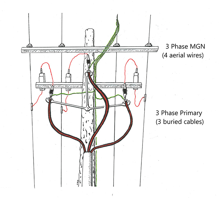
We all know the phrase “There is an exception to every rule”, well the circuit principle in electric current has an exception as well. The details are a little involved, but the exception itself is easy to write – not all 3 phase current requires a circuit. Because the 3 primaries are in different phases, 3 phase power can be placed using just 3 total conductors. This is often seen on aerial 3 phase. There will be only 3 total conductors on the line, not 6 as you might expect. Nor will there be 4 conductors as we see with MGN (Multi Ground Neutral) arrangements. This is the biggest reason why identifying aerial power correctly can be confusing.
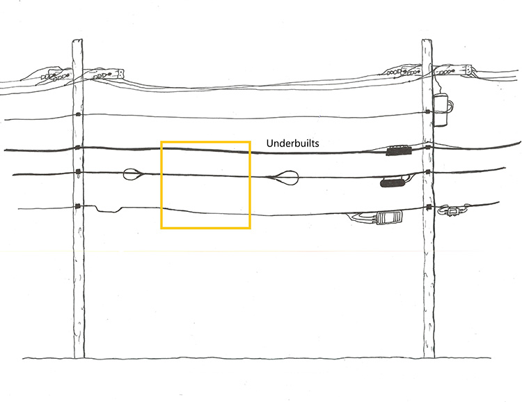
With distribution power we usually see something quite different. In a typical layout, there will be three aerial wires running parallel to each other, then another wire slung lower on the pole line. This is 3-phase power with 4 aerial wires. This is because the fourth wire, the lower wire, is a shared neutral. The 3 parallel wires are all hot wires, all carrying electricity to your house. But the fourth wire is the return wire, the neutral wire for the path back to the substation. In other words, 3-phase is separate on the hot wires, but shared on the neutral wire. This is called Multi-Grounded Neutral, or MGN.
However, some confusion can come from a slight difference in the pole layout. Although with most MGN the hot wires are as previously described, all parallel to each other, and the neutral wire below, but that is not always the case. On some distribution pole lines you will be able to see 4 aerial wires running parallel with each other. This has given rise to the mistaken belief that there must be 4-phase power, but there is no such thing as 4-phase power.
What we are seeing with 4 aerial wires side by side is no different than the other arrangement, except that the neutral wire is running parallel with the others, instead of below them. This is very apparent, but also very difficult to see from the ground. However, it is easiest to recognize at any pole where the 3-phase lines come down the pole. At that point, the neutral wire is connecting with each one of the primary cables going down the pole, and has an additional wire running down the side of the pole to ground, hence the name Multi-Grounded Neutral.
Therefore, there are four aerial power wires running pole to pole, but only 3 power primaries coming down from the pole. Three of the aerial wires are hot wires, each feeding to a different primary, and the fourth is the shared neutral with 4 separate small wires, three running to the primaries, and the fourth running down in to the earth as a ground wire.
On aerial power cables, the higher the voltage on the line, the more spacing there will be between the cables. There will also be an increase in the distance to the ground. This is why transmission towers are so high off the ground. The higher the voltage, the more spacing required.
Although this is very noticeable on aerial lines, the same principle is followed for underground power lines. However, buried primary cables have a thick black jacket of insulation, so the distance between primaries does not need to be anywhere near the distance they would be in the air.
Although buried 3-phase primaries are laid side by side, they are usually placed a distance apart from each other, much the same way as they are placed aerially. A typical 3-phase primary may have the conductors spaced a foot apart from each other, but higher voltage 3-phase may have the primary cables spaced as much as 3 feet apart. Again, this will not be the same distance that the cables would be if they were aerial.
Electric power can often be placed in a conduit or duct structure. In some areas, conduits are mandatory for power cables, in other areas they may only be mandatory in certain conditions. Besides plastic and steel conduits, they may also be placed within concrete or asbestos cement duct runs. This is becoming more common as buried transmission power is becoming more common.
On buried high voltage transmission lines the cables may be in a very thick duct of concrete, with only occasional manhole access.
Power cables went through a history of design similar to telephone cables, a wide variety of strange materials being used. In 1872 paper insulation was first used for power cables. Often these cables had an outer insulation of natural rubber which was processed from rubber trees from South America, while others were inserted in to lead or iron pipes.
By about 1887 the PILC cable was becoming a common design, especially for power cables used for carrying up to 25,000 volts. This was the Paper Insulated Lead Cable, made by wrapping the conductor in paper tape, inserting this in to a lead pipe, and then immersing the pipe in to wax, and then hot oil. The paper inside the cable then was soaked with wax, which when it dried, created a filled interior to the lead. PILC cables were the common power cable from about 1887.